SERVICE MANUAL
Parts marked with " " are important for maintaining the safety of the set. Be sure to replace these parts with specified ones for maintaining the
safety and performance of the set.
This document has been published to be used for
after sales service only.
The contents are subject to change without notice.
NOTE AND MODIFIED PARTS LIST
NOTE ..................................................................i
MODIFIED PARTS LIST .....................................i
Item of modified contents ....................................i
SAFETY PRECAUTION
IMPORTANT SERVICE SAFETY PRE-
CAUTION ...........................................................ii
PRECAUTIONS A PRENDRE LORS DE
LA REPARATION .............................................. iii
PRECAUTIONS FOR USING LEAD-FREE
SOLDER ...........................................................iv
PRECAUTIONS IN SERVICING THE
HDCP-KEY ROM ..............................................iv
CHAPTER 1. OPERATION MANUAL
[1] SPECIFICATIONS ......................................... 1-1
[2] OPERATION MANUAL .................................. 1-2
[3] DIMENSIONS ................................................ 1-8
CHAPTER 2. REMOVING OF MAJOR PARTS
[1] REMOVING OF MAJOR PARTS
(LC-42D64U).................................................. 2-1
[2] REMOVING OF MAJOR PARTS
(LC-46/52D64U)............................................. 2-7
CHAPTER 3. ADJUSTMENT
[1] ADJUSTMENT PROCEDURE ....................... 3-1
CHAPTER 4. TROUBLESHOOTING TABLE
[1] TROUBLESHOOTING TABLE ......................4-1
CHAPTER 5. MAJOR IC INFORMATIONS
[1] MAJOR IC INFORMATIONS .........................5-1
CHAPTER 6. OVERALL WIRING/BLOCK DIAGRAM
[1] OVERALL WIRING DIAGRAM
(LC-42D64U) .................................................6-1
[2] OVERALL WIRING DIAGRAM
(LC-46/52D64U) ............................................6-3
[3] SYSTEM BLOCK DIAGRAM.........................6-5
CHAPTER 7. PRINTED WIRING BOARD ASSEM-
BLIES
[1] MAIN Unit ......................................................7-1
[2] TERMINAL Unit .............................................7-9
[3] SIDE Unit..................................................... 7-11
[4] R/C, LED Unit ..............................................7-13
[5] KEY Unit ......................................................7-14
CHAPTER 8. SCHEMATIC DIAGRAM
[1] DESCRIPTION OF SCHEMATIC DIA-
GRAM............................................................8-1
[2] SCHEMATIC DIAGRAM ................................8-2
Parts Guide
TopPage
CONTENTS
This service manual is issued since the main and side PWBs used for LC-42/46/52D64U have been changed. For the
product where the main and side PWBs have been changed, refer to the following serial No. for each model.
Model name/Serial No. LC42D64U: 712851112~/LC46D64U: 712891112~/LC52D64U: 712871112~.
No. SX7B5LC42D64U
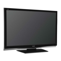
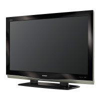
MODELS
LC-42D64U
LC-46D64U
LC-52D64U
LCD COLOR TELEVISION
In the interests of user-safety (Required by safety regulations in some countries) the set should be restored to its orig-
inal condition and only parts identical to those specified should be used.
NOTE
LC-42D64U/46D64U/52D64U
Revised Edition