LC-60/70LE650U/C6500U/LE657U,LC-60/70LE755U/LE757U/LE857U/C7500U
4 – 21
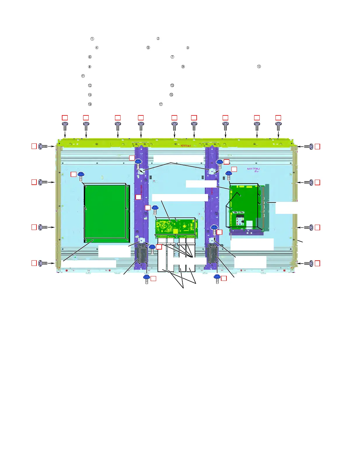
4. Removing of Frame Ass'y, LCD CONTROL Unit, MAIN Unit, POWER/DRIVE Unit, VESA Angle Ass'y and Stand
Angle.
1. Remove the 17 lock screws and Detach the Frame Ass'y .
2. Remove the 2 FFC80P Cords and 2 FFC64P Cords , 4 Ferrite Cores .
3. Remove the 6 lock screws and detach the LCD CONTROL Unit .
4. Remove the 8 lock screws and detach the Terminal Angle Side Ass'y and Terminal Angle Bottom Ass'y .
5. Remove the MAIN Unit .
6. Remove the 6 lock screws and detach the POWER/DRIVE Unit .
7. Remove the 4 lock screws and detach the 4 VESA Angle Ass'y .
8. Remove the 8 lock screws and detach the 2 Stand Angles .
12
12
8
1
1
1
1
1
1
1
1
ԙFrame
Ass'y
ԚFerrite Core
ԛFFC80P
ԜFFC64P
ԞLCD CONTROL Unit
ԠTerminal Angle
Side Ass'y
ԡTerminal Angle
Bottom Ass'y
MAIN UnitԢ
ԤPOWER/DRIVE Unit
14
14
14
14
Ԧ8'5##PING#UU[
Ԧ8'5##PING
#UU[
Ԧ8'5##PING
#UU[
16
16
5VCPF#PINGԨ
Ԩ5VCPF#PING