EasyManua.ls Logo

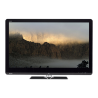
Sharp LC-60LE831U - User Manual

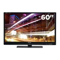
Sharp LC-60LE831U
110 pages
To Next Page IconTo Next Page
Loading...
SERVICE MANUAL
LC-40/46/52/60LE835U/830U/832U/LC-60LE831U
Parts marked with " " are important for maintaining the safety of the set. Be sure to replace these parts with specified ones for maintaining the
safety and performance of the set.
This document has been published to be used for
after sales service only.
The contents are subject to change without notice.
SAFETY PRECAUTION
IMPORTANT SERVICE SAFETY PRECAUTION
...............i
PRECAUTIONS A PRENDRE LORS DE
LA REPARATION...............................................ii
PRECAUTIONS FOR USING LEAD-FREE SOLDER
........... iii
OUTLINE
MAJOR SERVICE PARTS ................................iv
CHAPTER 1. SPECIFICATIONS
[1]
SPECIFICATIONS (LC-40/46LE835U/830U/832U)
......... 1-1
[2] SPECIFICATIONS (LC-52/60LE835U/
830U/832U/LC-60LE831U) ............................ 1-2
CHAPTER 2. OPERATION MANUAL
[1] Parts Name .................................................... 2-1
[2] OPERATION MANUAL .................................. 2-3
CHAPTER 3. DIMENSIONS
[1]
DIMENSIONS (LC-40LE835U/830U/832U)
........ 3-1
[2]
DIMENSIONS (LC-46LE835U/830U/832U)
........ 3-2
[3]
DIMENSIONS (LC-52LE835U/830U/832U)
........ 3-3
[4]
DIMENSIONS (LC-60LE835U/830U/831U/832U)
........ 3-4
CHAPTER 4. REMOVING OF MAJOR PARTS
[1] REMOVING OF MAJOR PARTS
(LC-40LE835U/830U/832U)........................... 4-1
[2] REMOVING OF MAJOR PARTS
(LC-46LE835U/830U/832U)........................... 4-6
[3] REMOVING OF MAJOR PARTS
(LC-52LE835U/830U/832U)......................... 4-11
[4] REMOVING OF MAJOR PARTS
(LC-60LE835U/830U/831U/832U)...............4-16
[5]
The location putting on the heat measure sheet
......4-21
[6] Precautions for assembly ............................4-24
[7] The way of detaching Rear Cabinet ............4-26
CHAPTER 5. ADJUSTMENT
[1] ADJUSTMENT PROCEDURE ......................5-1
[2]
PUBLIC MODE SETTING PROCEDURE
.......5-16
CHAPTER 6. TROUBLESHOOTING TABLE
[1]
Failure diagnosis by LED in front of cabinet
........6-1
[2] LED flashing specification at the time of an
error (Center icon LED used) ........................6-1
[3] TROUBLESHOOTING TABLE ......................6-5
CHAPTER 7. MAJOR IC INFORMATIONS
[1] MAJOR IC INFORMATIONS .........................7-1
CHAPTER 8. OVERALL WIRING/SYSTEM BLOCK DIAGRAM
[1] OVERALL WIRING DIAGRAM
(LC-40/46/52/60LE835U) ..............................8-1
[2] OVERALL WIRING DIAGRAM (LC-40/46/
52/60LE830U/832U/LC-60LE831U) ..............8-2
[3] SYSTEM BLOCK DIAGRAM
(LC-40/46/52/60LE835U) ..............................8-3
[4] SYSTEM BLOCK DIAGRAM (LC-40/46/
52/60LE830U/LE832U/LC-60LE831U)..........8-4
Parts Guide
CONTENTS
In the interests of user-safety (Required by safety regulations in some countries) the set should be restored to its orig-
inal condition and only parts identical to those specified should be used.
No. S21M760LE835U
LCD COLOR TELEVISION
LC-60LE831U
LC-40/46/52/60LE835U
LC-40/46/52/60LE830U
LC-40/46/52/60LE832U
MODELS
Question and Answer IconNeed help?

Do you have a question about the Sharp LC-60LE831U and is the answer not in the manual?

Sharp LC-60LE831U Specifications

General IconGeneral
Screen Size60 inches
Display TechnologyLCD
Backlight TypeLED
Refresh Rate120 Hz
3DYes
Smart TVYes
HDMI Ports4
USB Ports2
Wi-FiYes
Ethernet PortYes
Component Video Input1
Composite Video Input1
Display TypeLED
Resolution1920 x 1080
Audio OutputOptical

Summary

Safety Precautions

Important Service Safety Precautions

Critical safety measures and guidelines for service personnel, emphasizing adherence to safety checks.

Safety Notice

Highlights special safety-related characteristics of electrical and mechanical parts in LCD TVs.

Precautions for Using Lead-Free Solder

Employing Lead-Free Solder

Information on the use of lead-free solder, symbols, and types.

Using Lead-Free Wire Solder

Guidance on applying lead-free wire solder and recommendations for soldering bits.

Soldering Precautions

Tips and precautions for handling and soldering with lead-free solder.

Outline

Major Service Parts

Lists main service parts, including PWB units, other units, and ICs for service.

Service Jigs

Lists specialized jigs used for servicing the equipment.

Chapter 1. Specifications

Specifications for LC-40;46;52;60 LE835 U;830 U;832 U

Detailed specifications for the LC-40, 46, 52, and 60LE835U/830U/832U models.

Specifications for LC-52;60 LE835 U;830 U;832 U;LC-60 LE831 U

Detailed specifications for the LC-52, 60LE835U/830U/832U, and LC-60LE831U models.

Chapter 2. Operation Manual

Parts Name Identification

Identifies and labels the various parts of the TV's front and rear.

Remote Control Unit Functions

Explains the function of each button on the remote control unit.

Attaching the TV Stand

Provides step-by-step instructions for safely attaching the television stand.

Chapter 3. Dimensions

Dimensions for LC-40 LE835 U;830 U;832 U

Provides physical dimensions and mounting details for specific models.

Dimensions for LC-46 LE835 U;830 U;832 U

Provides physical dimensions and mounting details for specific models.

Dimensions for LC-52 LE835 U;830 U;832 U

Provides physical dimensions and mounting details for specific models.

Dimensions for LC-60 LE835 U;830 U;831 U;832 U

Provides physical dimensions and mounting details for specific models.

Chapter 4. Removing of Major Parts

Removing Major Parts for LC-40 LE835 U;830 U;832 U

Step-by-step guide for removing major parts from specific TV models.

Removing Major Parts for LC-46 LE835 U;830 U;832 U

Step-by-step guide for removing major parts from specific TV models.

Removing Major Parts for LC-52 LE835 U;830 U;832 U

Step-by-step guide for removing major parts from specific TV models.

Removing Major Parts for LC-60 LE835 U;830 U;831 U;832 U

Step-by-step guide for removing major parts from specific TV models.

Heat Measure Sheet Placement

Instructions on where to place heat measure sheets on the main PWB.

Assembly Precautions

Guidelines and precautions for proper assembly procedures.

Detaching the Rear Cabinet

Detailed procedure for safely removing the rear cabinet.

Chapter 5. Adjustment

Adjustment Procedure Overview

General procedures and notes for performing adjustments after part replacement.

Microprocessor Software Upgrading

Instructions for upgrading the unit's main and monitor microprocessor software.

Entering and Exiting Adjustment Mode

Steps to enter and exit the service adjustment process mode.

Adjustment Mode: Controller and Display

Explains remote controller key operations and display elements in adjustment mode.

Adjustment Process Mode Menu List

A comprehensive list of adjustment items, their descriptions, and remarks.

Special Features and Settings

Details on special features like standby cause, EEP save/recover, and signal adjustment.

White Balance Adjustment

Procedure for performing white balance adjustments on the display.

Key Writing Procedures

Instructions for writing EDID, MAC, and NETFLIX/WMDRM keys.

Factory Setting and Software Version

Steps for factory settings and checking software versions.

Public Mode Setting Procedure

Steps to start, exit, and configure settings in public mode.

On Setting Items Configuration

Details on various configurable setting items like volume and input modes.

Chapter 6. Troubleshooting Table

Failure Diagnosis by Front LED

Diagnosing TV issues based on the status of the front cabinet LED.

LED Flashing Specifications for Errors

Details on LED flashing patterns used to indicate specific error conditions.

New Troubleshooting Methods

Describes new methods for troubleshooting and error analysis.

Troubleshooting: No Picture

Diagnostic steps for issues where the picture does not display.

Troubleshooting: No Sound

Diagnostic steps for issues where there is no audio output.

Chapter 7. Major IC Informations

Major Integrated Circuit Information

Lists and describes the key integrated circuits (ICs) used in the television.

Chapter 8. Wiring and Block Diagrams

Overall Wiring Diagram (LC-40;46;52;60 LE835 U)

Illustrates the wiring connections for specific TV models.

Overall Wiring Diagram (LC-40;46;52;60 LE830 U;832 U;LC-60 LE831 U)

Illustrates the wiring connections for other TV models.

System Block Diagram (LC-40;46;52;60 LE835 U)

Shows the system's functional blocks and their interconnections.

System Block Diagram (LC-40;46;52;60 LE830 U;832 U;LC-60 LE831 U)

Illustrates system block diagrams for other TV models.

Parts Guide

Printed Wiring Board Assemblies

Lists part numbers for various printed wiring board assemblies.

LCD Panel Module Units

Lists part numbers for the LCD panel module units.

Cabinet Parts for LC-40;46;52 LE835 U;830 U;832 U

Lists cabinet parts for specific TV models.

Cabinet Parts for LC-46 LE835 U;830 U;832 U

Lists cabinet parts for specific TV models.

Cabinet Parts for LC-52 LE835 U;830 U;832 U

Lists cabinet parts for specific TV models.

Cabinet Parts for LC-60 LE835 U;830 U;831 U;832 U

Lists cabinet parts for specific TV models.

Supplied Accessories;Packing Parts for LC-40;46;52 LE835 U;830 U;832 U

Lists supplied accessories and packing parts for specific models.

Supplied Accessories;Packing Parts for LC-46 LE835 U;830 U;832 U

Lists supplied accessories and packing parts for specific models.

Supplied Accessories;Packing Parts for LC-52 LE835 U;830 U;832 U

Lists supplied accessories and packing parts for specific models.

Supplied Accessories;Packing Parts for LC-60 LE835 U;830 U;831 U;832 U

Lists supplied accessories and packing parts for specific models.

Service Jigs

Lists specialized jigs used for servicing the equipment.

Related product manuals