QUICK REFERENCE
3
n LC- 70LE657U/LC-60LE657U/LC- 70LE655U/
LC-60LE655U/LC-70LE650U/LC-60LE650U/
LC- 70C6500U/LC-60C6500U
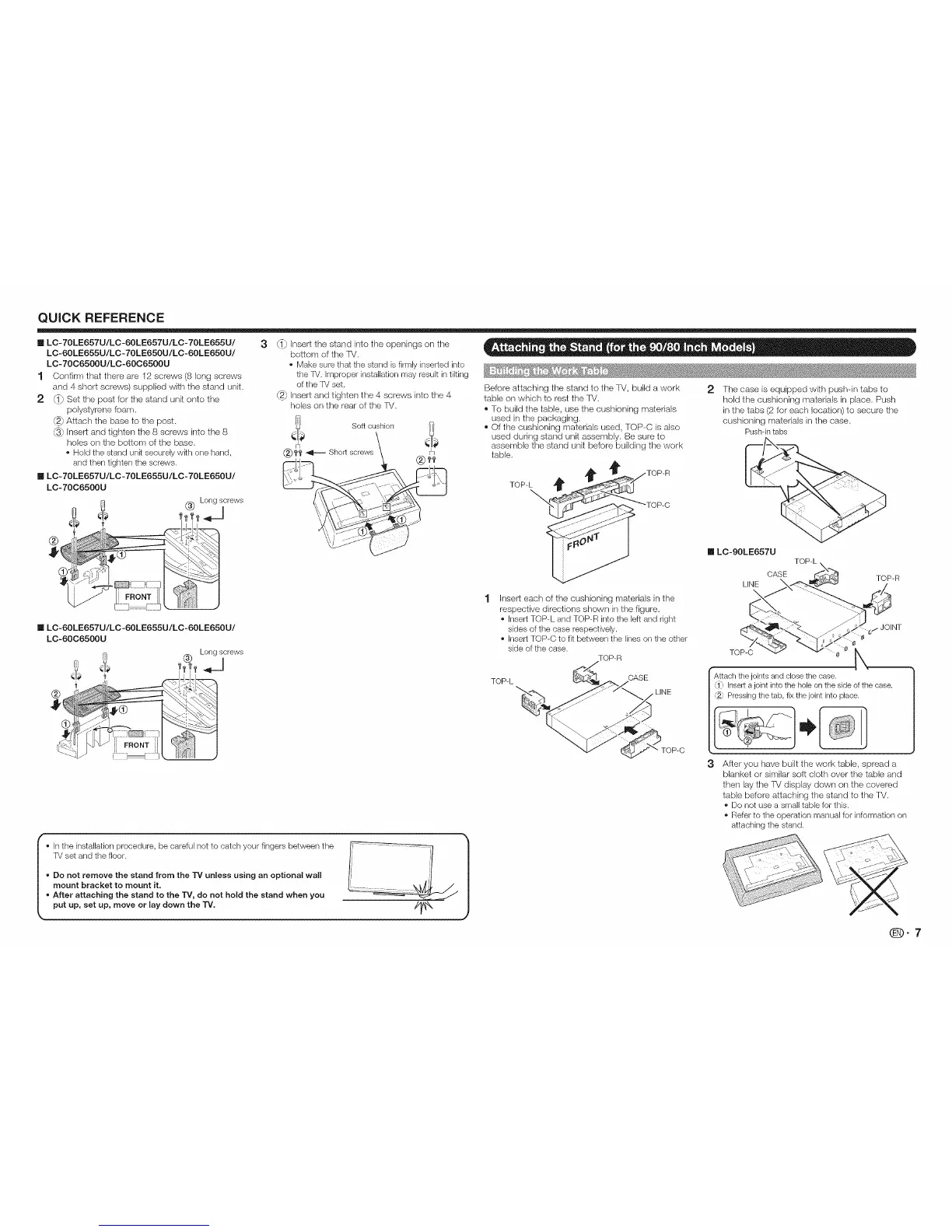
1 Confirm that there are 12 screws (8 long screws
and 4 short screws) supplied with the stand unit.
2 _} Set the post for the stand unit onto the
polystyrene foam.
@_Attach the base to the post.
@_Insert and tighten the 8 screws into the 8
holes on the bottom of the base.
• Hold the stand unRsecurely wRh one hand,
and then tighten the screws.
m LC- 70LE657U/LC -70LE655U/LC- 70LE650U/
LC-70C6500U
_ (_) Longscrews
®
_} Insert the stand into the openings on the
bottom of the fV.
• Make sure that the stand is firmly inserted into
the TV. Improper installation may result in tilting
of the TV set.
@_ Insert and tighten the 4 screws into the 4
holes on the rear of the FV.
Soft cushion
®I'f' _ Short screws
Before attaching the stand to the TV, build a work 2 The case is equipped with push-in tabs to
table ors which to rest the FV. hold the cushioning materials in place. Push
® To build the table, use the cushioning materials in the tabs (2 for each location) to secure the
used in the packaging, cushioning materials in the case.
® Of the cushioning materials used, TOP-C is also
Pushqn tabs
used during stand unit assembly. Be sure to
assemble the stand unit before building the work
table.
TOP-L _TOP-R
__ _TOP-C I LC-90LE657U TOP-L
CASE
LINE \ TOP-R
n LC-60LE657U/LC -60LE655U/LC-60LE650U/
LC-60C6500U
Long screws
!÷
®
I o In the installation procedure, be careful not to catch your fingers between the V ..... _ |
TV set and the floor. ]i '[ /
o Do not remove the stand from the 13' unless using an optional wall I; ,'I |
mount bracket to mount it. [' \_,!_J, / l
o After attaching the stand to the TV, do not hold the stand when you _--_=_--_'___ |
put up, set up, move or lay down the "iV. //_ )
Insert each of the cushioning materials in the
respective directions shown in the figure.
• Insert TOP-L and TOP-R into the left and right
sides of the case respectively.
• Insert TOP-C to fit between the lines on the other
side of the case.
TOP-R
TOP-L
CASE
LINE
TOP-C
_,/JOINT
0
TOP-C _ 0
Attach the joints and close the case.
1_ Insert a joint into the hole on the side of the case.
Pressing the tab, fix the joint into place.
I
3 After you have built the work table, spread a
blanket or similar soft cloth over the table and
then lay the TV display down ors the covered
table before attaching the stand to the TV.
• Do not use a small table for this.
• Refer to the operation manual for information on
attaching the stand.
qD-7