MX3500N PAPER EXIT SECTION O – 2
2. Operational descriptions
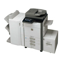
A. Paper exit section
• Paper transported from the fusing section is passed to the trans-
port roller 13 which is driven by the paper exit drive motor and to
the paper exit roller 1, then discharged to the inner tray.
• When paper is discharged to the right tray, it is passed to the
paper exit roller 1 and the paper exit drive motor is reversely
rotated, and paper is passed over the ADU reverse gate and dis-
charged to the right tray.
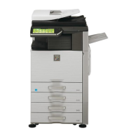
3. Disassembly and assembly
A. Paper exit section
(1) Paper exit unit
1) Remove the screw, the upper cabinet right, and the right con-
necting cabinet.
2) Remove the fusing unit.
3) Remove the screw, and remove the paper exit unit, and dis-
connect the connector.
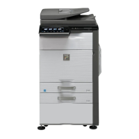
a. Exit paper full detection sensor
b. Shifter home position detection sensor
1) Remove the paper exit unit.
c. Paper exit detection sensor
d. After-fusing sensor
1) Remove the paper exit unit.
2) Paper exit sensor (A), after-fusing sensor (B)
e. Paper exit cooling fan motor
1) Remove the paper exit unit.
2) Remove the exhaust fan duct.
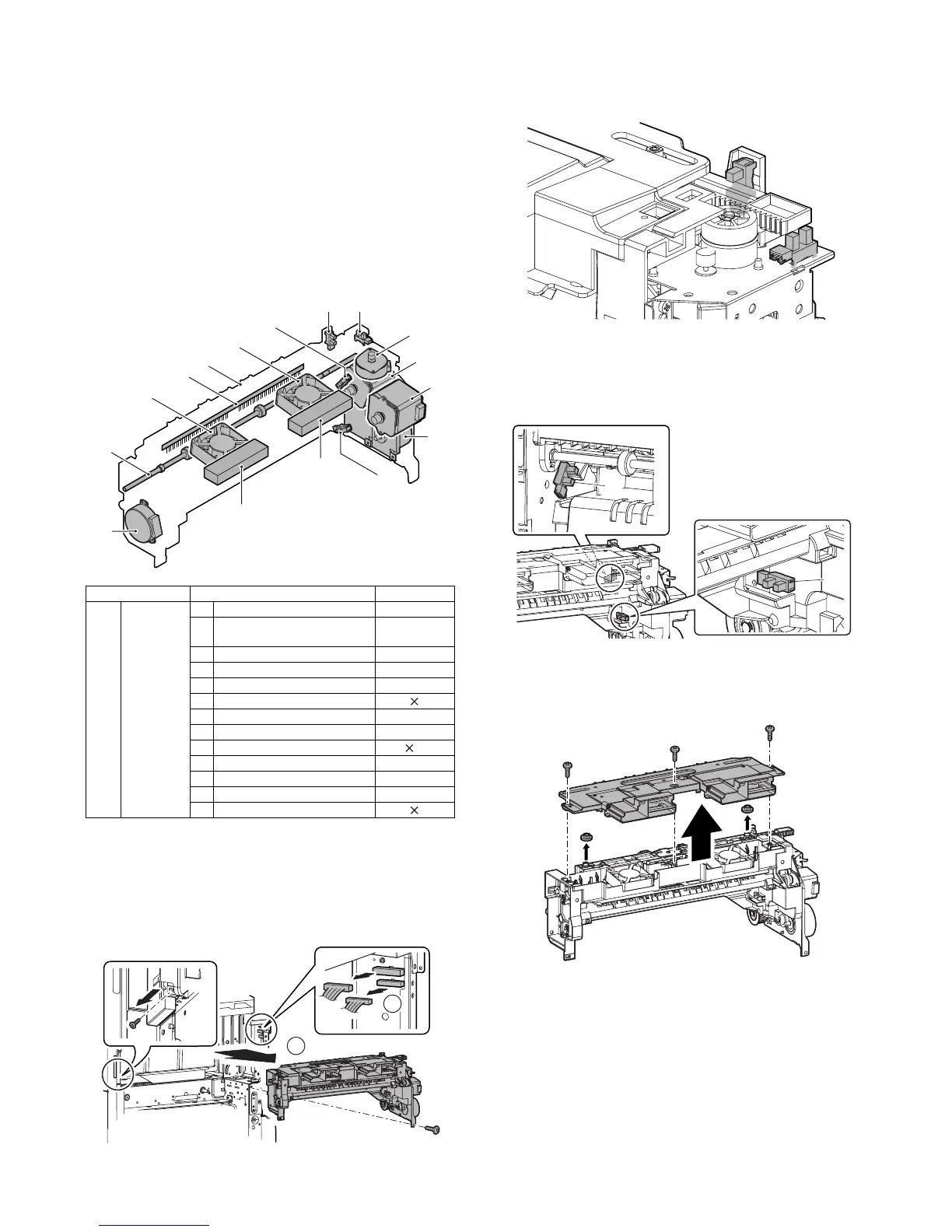
Unit Parts Maintenance
(1) Paper exit
unit
a Exit paper full detection sensor
b Shifter home position detection
sensor
c Paper exit detection sensor
d After-fusing sensor
e Paper exit cooling fan motor
f Discharge brush
g Shifter motor
h Fusing web cleaning motor
i Paper exit roller 1 (Drive) {
j Fusing drive motor
k Paper exit drive motor
l ADU motor upper
m Paper exit filter
(1)
(1)-k
(1)-c
(1)-a
(1)-m
(1)-b
(1)-g
(1)-j
(1)-i
(1)-f
(1)-e
(1)-h
(1)-e
(1)-d
(1)-l
(1)-m
1
2
A
B