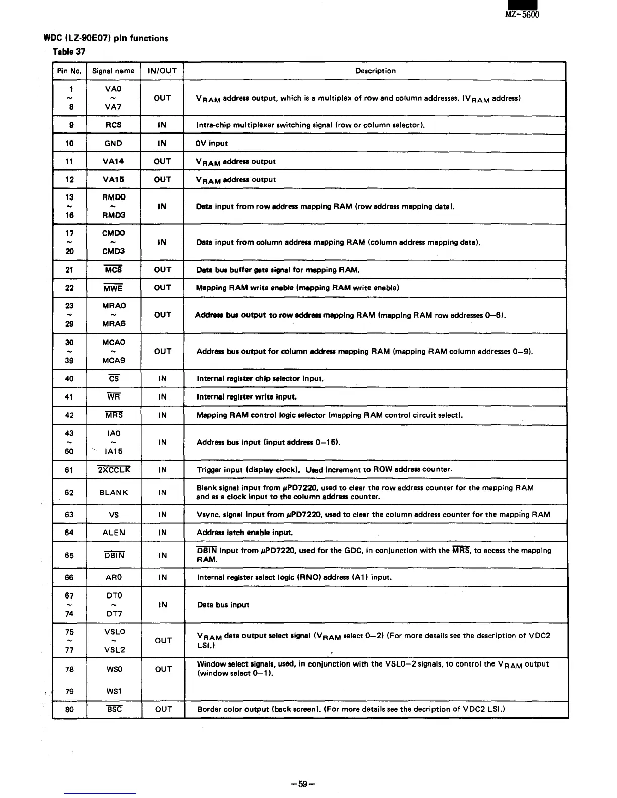
woe
(LZ-90E07) pin functions
Table
37
Pin
No.
Signal name
IN/OUT
1
VAO
-
-
OUT
8
VA7
9
RCS
IN
10
GND
IN
11
VA14
OUT
12
VA15
OUT
13
RMDO
-
-
IN
18
RMD3
17 CM
DO
- -
IN
20
CMD3
21
MCS
OUT
22
MWE
OUT
23
MRAO
-
-
OUT
29
MRA6
30
MCAO
-
-
OUT
39
MCA9
40
CS
IN
41
WR
IN
42 MRS IN
43
IAO
-
-
IN
60
,
IA15
61
2XCCLI< IN
62
BLANK
IN
63
VS
IN
64
ALEN
IN
65
'i5BTN'
IN
66
ARO
IN
87
DTO
-
-
IN
74
OT7
75
VSLO
-
-
OUT
77
VSL2
78
WSO
OUT
79
WS1
80
BSC
OUT
-
MZ-5600
Description
V
RAM
address
output,
which
is
a
multiplex
of
row
and column
addresses.
(V
RAM
address)
Intra-chip
multiplexer
switching signal
(row
or
column selector).
OV
input
V
RAM
address
output
VRAM
address
output
Data
input
from
row
address mapping
RAM
(row
address mapping deta),
Data
input
from
column address mapping
RAM
(column address mapping data),
Data
bus
buffer
gate signal
for
mapping
RAM.
Mapping
RAM
write
enable (mapping
RAM
write
enable)
Address bus
output
to
row
address mapping
RAM
(mapping
RAM
row
addresses
0-6).
Address bus
output
for
column address mapping
RAM
(mapping
RAM
column
addresses
0-9).
Internal regi.ter
chip
selector
input.
Internal regi.ter
write
input,
Mapping
RAM
control
logic
.elector
(mapping
RAM
control
circuit
select).
Address bus
input
(input
address
0-15).
Trigger
input
(display clock). Used Increment
to
ROW address counter.
Blank signal
input
from
"PD7220,
used
to
clear the
row
address counter
for
the mapping
RAM
and
as
a
clock
input
to
the column address counter.
Vsync.
signal
input
from
"PD7220,
used
to
clear the column address counter
for
the mapping
RAM
Address latch enable input_
DBIN
input
from
"PD7220,
used
for
the GDC, in conjunction
with
the
MRS,
to
access
the mapping
RAM.
Internal register select logic (RNO) address
(A
1)
input.
Data bus
input
VRAM
data
output
select signal
(VRAM
select
0-2)
(For more details
see
the description
of
VOC2
LSI.)
Window
select Signals, used,
in
conjunction
with
the
VSLO-2
signals,
to
control
the V
RAM
output
(window
select
0-1
I.
Border
color
output
(back screen).
(For
more details
see
the decription
of
VOC2 LSI.)
-59-