EasyManua.ls Logo

Sharp PC-1350 User Manual

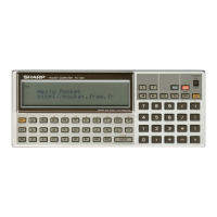
Sharp PC-1350
36 pages
To Next Page IconTo Next Page
Page #1 background imageLoading...
Page #1 background image
LCD display
(1) Text display
5 x 7
dot
matrix (24 x 4
lines)
(2) Graphic display
150 x 32 full
dot
display
Character size:
4.01 (H) x 2.85(W) mm
Character pitch:
3.48
(1
dot
space) mm
Dot size:
..ni '""
I
l1'i"3
'"4-LQ.05mm
r2?J
~=10.53mm
H~
0 0
~~~
•Display:
•Serial
i/
o
funct
i
on:
Communicat
i
on
method
:
Asynchronous (half-duplex
only
)
Baud rate:
300,600,
1200
Parity
bit
:
Even, odd, free
Word
length
:
7 or 8 bits
Stop bit:
1
or 2 bits
Connector:
15
-
pin, for
connec
-
tion with external
unit
Output
signal level:
CMOS level (4-6 volts)
Interfacing signals:
Input: RD, CS, CD
Output:
SD, RS, RR, ER
Others: SG, FG, VC
•Memory protection:
Program,
data,
reserve areas are
backed up by
battery
during power
off.
BASIC
CMOS 8-bit CPU
40 Kilobytes
System area: Approx. 1.6 kilobytes
Data area: 208 bytes
Program
/
data
area
:
3070
bytes
Rese
r
ve
area
:
144 bytes
Subroutine
:
1
0 stages
F
OR-NEXT: 5 stages
Funct
i
on
:
1
6stages
Data: 8 stages
Fundamental:
Four math rules
Functions
:
Trigonometric
,
reverse trigono-
metric,loga
r
ithm,
exponential,
angular
transformation,
power
rising, square
root,
integer, abso-
lute
value
,
signum
function,
circular
constant
Hor
i
zontal cursor
contro
l
(""
.
'4)
Insertion (INS)
Delet
i
on (DEL)
Line up and down
I
.l
,
t
)
SHARP CORPORATION
Editing
functions:
Basic calculator
functions
:
Stack
registers
:
Programming
language
:
•Microprocessor
:
System ROM:
Memory capacity:
Arithmetic
capac
i
ty
: 1
0
d
i
g
i
ts
(
man
tis
sa
)
+
2 digits
(
exponent
)
•Ar
i
thmet
i
c
method
:
In
o
r
der
o
f mathematical expres-
s
i
on
(
with
prior
i
ty
determination
f
unct
i
on)
P
C
-1
350
!
11
#
$
%
&
?
>r
I
@
8~~0~00~0~0
l
oErl
GJ
0 [£] [!] 0
GJ
GJ
[TI
CD
c:J
P
-
NP
@MW
0 0 ~ 0 ~ 0 ~ ~
I
ENTER
I
S
ML
~~
~~~~~~~~~~
~~~~~~~
l';HIIT
DEF
GRAPHIC 150
x
32
dot
OJ
[!]
TEXT
24
x
4 lines
POWER ON
Foo
E
I I
cc
L
~
I
[l
ON
O
FF
8J
[8
l
nEL
I
l
!Ns
l
IBRKI
~
< >
0~GCJ0
0G~DD
GJ000D
"
GDGDD
R
UN
PRO
CE-516L
CE-202M
CE-201M
PC-1350
MODEL
CODE:
OOZPC1350SM
/
E
•Mode
l
Keyboard
layout
1.
SPECIFICATIONS
SERVICE
MANUAL
SHARP
-
PC-1350
Question and Answer IconNeed help?

Do you have a question about the Sharp PC-1350 and is the answer not in the manual?

Sharp PC-1350 Specifications

General IconGeneral
ModelPC-1350
CategoryPDA
KeyboardAlphanumeric
Programming LanguageBasic
Release Year1983
DisplayLCD
Power Supply4×AA batteries

Summary

1. SPECIFICATIONS

Keyboard Layout

Describes the physical arrangement of keys on the PC-1350.

Model Information

Identifies the specific model number of the device.

Arithmetic Specifications

Details capacity, method, and precision of calculations.

Programming Language

Indicates the primary programming language supported.

Microprocessor and ROM

Identifies the CPU and specifies the size of the built-in ROM.

Memory Capacity Details

Details the available memory for programs and data.

Stack Registers

Outlines the different types and depths of stack registers.

Basic Calculator Functions

Lists fundamental mathematical and scientific functions.

Editing Functions

Describes text and program editing capabilities.

Serial I/O Function

Explains serial communication parameters and interface signals.

Memory Protection

Details how data is preserved during power loss.

Display Characteristics

Specifies display characteristics, including text and graphic modes.

2. SYSTEM CONFIGURATION

Power and Battery Details

Covers auto-power-off, operating temp, power supply, and battery life.

Physical and Accessory Information

Details physical dimensions, weight, accessories, and options.

4. BATTERY LIFE AND POWER CONSUMPTION

Battery Life Conditions

Provides detailed battery life conditions and retention times.

Power Consumption Levels

Lists power consumption values for different operating states.

Battery Replacement Guidance

Explains how to determine when batteries need replacement.

RAM Card Battery Note

Provides a note on replacing RAM card batteries.

5. RAM MAP

Memory Address Map

Illustrates the memory address map for ROM and RAM cards.

6. CAUTIONS IN USING THE RAM CARD OPTION

Program/Data Area Capacity

Shows program/data area capacities with different RAM cards.

Holding Data on RAM Card

Explains methods for retaining data on RAM cards.

MEM "C" Command Setup

Describes how to manage RAM card setups using MEM "C" command.

Caution: RUN Command Usage

Warns about data loss when using the RUN command.

RAM Card and PC-1350 Program Interaction

Explains how PC-1350 programs interact with RAM cards.

7. USE OF TEST PROGRAM

Memory Test Program Details

Details built-in test programs for CPU ROM and external ROM.

8. LSI DESCRIPTIONS

SC61860A Microprocessor Signals

Provides detailed descriptions of the SC61860A LSI signals.

Display and Key Input Tests

Describes tests for display output and key input functionality.

Key Code Chart

Key Code Chart Reference

Table mapping display codes to corresponding keys.

I/O Circuit Tests

Serial I/O Functionality Test

Details tests for serial I/O functionality using test programs.

SC43537 Display LSI Description

Display LSI Timing Diagrams

Illustrates timing diagrams for the SC43537 display LSI.

Waveform Analysis

Counter and Segment Waveforms

Displays waveforms for counter and segment outputs.

SC60220 Gate Alley LSI

Gate Alley LSI Functionality

Describes the function of the SC60220 Gate Alley LSI.

9. RAM CARD

RAM Card Types and Specs

Details types and specifications of RAM cards.

RAM Card Board Removal

Provides instructions for safely removing RAM card boards.

RAM Card Power Consumption Test

Outlines the procedure for testing RAM card power consumption.

10. CIRCUIT DIAGRAM (1)

PC-1350 CPU Circuit Diagram

Shows the circuit diagram for the PC-1350 CPU.

2. PC-1350 Display Circuit

PC-1350 Display Circuit Diagram

Illustrates the circuit diagram for the PC-1350 display.

3. PC-1350 Memory Circuit (ROM: SC613256)

PC-1350 Memory Circuit Diagram

Shows the circuit diagram for the PC-1350 memory circuit.

4. PC-1350 Key/LCD Matrix Circuits

Key and LCD Matrix Circuit Diagram

Depicts the circuit diagram for key and LCD matrix components.

11. PARTS AND SIGNAL LAYOUT CHART (MAIN PWB)

Jumper Circuit Description

Explains the function of jumper circuits for RAM card data protection.

Parts and Signal Layout Chart (Memory PWB)

Jumper Circuit Description

Explains the function of jumper circuits for RAM card data protection.

12. CE-201M CIRCUIT DIAGRAM/PARTS LAYOUT CHART (FLAT PACKAGE LSI)

CE-201M Circuit and Parts Layout

Provides circuit and parts layout for the CE-201M.

13. CE-202M CIRCUIT DIAGRAM/PARTS LAYOUT CHART (FLAT PACKAGE LSI)

CE-202M Circuit and Parts Layout

Provides circuit and parts layout for the CE-202M.

14. CE-202M CIRCUIT DIAGRAM/PARTS LAYOUT CHART (PCOS TYPE)

CE-202M PCOS Type Circuit and Parts Layout

Provides circuit and parts layout for the CE-202M PCOS type.

15. CE-516L CIRCUIT DIAGRAM/PARTS LAYOUT CHART

15-Pin Connector Pin Description

Describes the pinout of the 15-pin connector for PC-1350 interface.

CE-516L Interface Signals

Lists part numbers and associated signals for interface.

16. PARTS LIST AND GUIDE

External Parts List

Lists external parts of the PC-1350 with part codes and descriptions.

Accessories and Other Parts

Lists accessories and other miscellaneous parts.

Accessories and Other Parts

Main PWB Unit Components

Lists components and specifications of the main PWB.

Memory PWB Unit Components

Lists components and specifications of the memory PWB.

CE201M/CE202M Options

Parts Codes for Options

Lists part codes for CE201M/CE202M options.

CE516L Option

Parts Codes for CE516L Option

Lists part codes for the CE516L option.

SUPPLEMENT & CORRECTION

Initialization Supplement

Provides supplementary information and correction procedures.

Related product manuals