Connections
Caution
• Besuretoturnoffthemainpowerswitchanddisconnecttheplugfromthepoweroutletbeforeconnecting/disconnecting
cables. Also, read the manual of the equipment to be connected.
• Becarefulnottoconfusetheinputterminalwiththeoutputterminalwhenconnectingcables.Accidentallyreversingcables
connected to the input and output terminals may cause malfunctions and the other problems.
TIPS
• SettheaudioinputterminalusedforeachinputmodeinAUDIOSELECTontheOPTIONmenu.Thefactorysettingsare
shown below.
Input mode Audio input terminal (Factory setting)
PCD-SUB,PCDVI-D,PCRGB
Audio input terminal
AVDVI-D Audio1 input terminal
AVCOMPONENT,
AVS-VIDEO,AVVIDEO
Audio2 input terminal
PCHDMI,AVHDMI PC/AVHDMIinputterminal
• Whenconnectingtheexternalspeaker,attachthespeakercablecore(includedintheoptionalPN-ZB02).
• HDMI,theHDMIlogoandHigh-DenitionMultimediaInterfacearetrademarksorregisteredtrademarksofHDMILicensing
LLC.
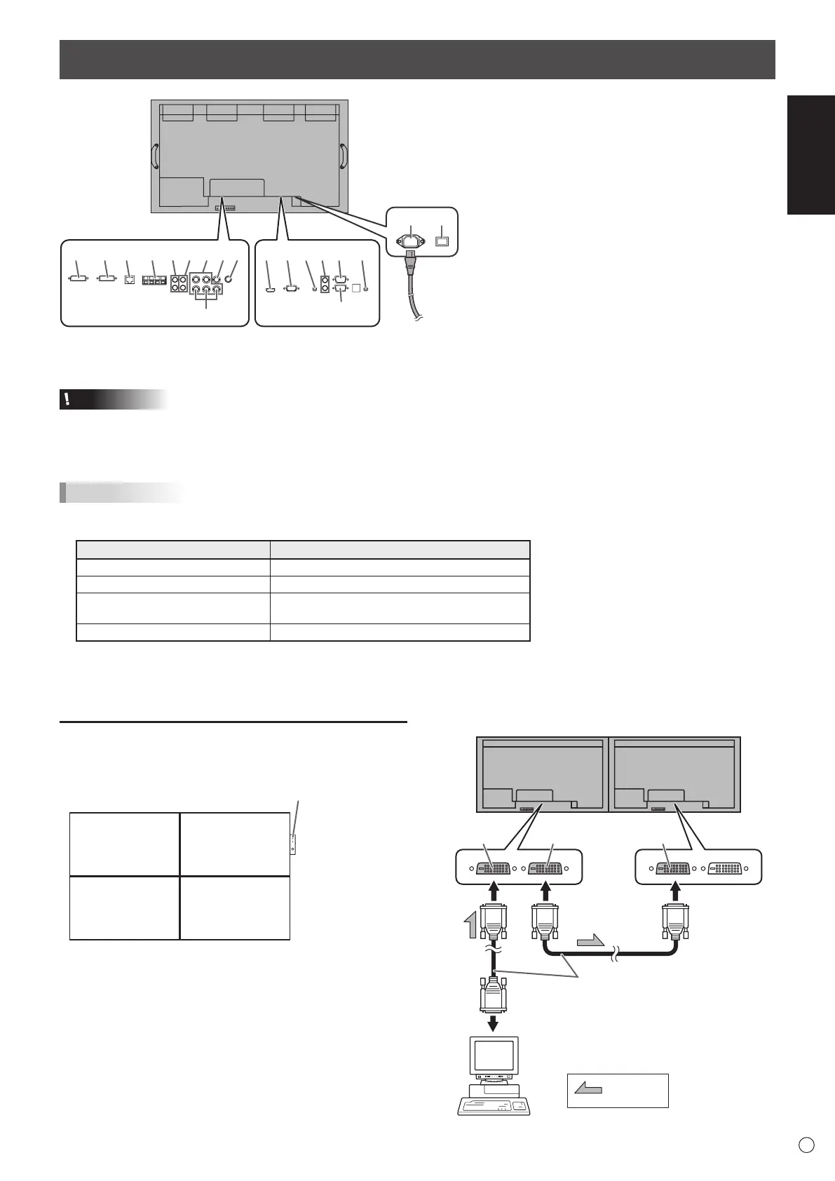
1. PC/AV HDMI input terminal
2. PC D-sub input terminal
3. Audio input terminal
4. Audio output terminals
5. RS-232C output terminal
6. RS-232C input terminal
7. Control kit terminal
8. PC/AV DVI-D input terminal
9. PC/AV DVI-D output terminal
10. LAN terminal
11. External speaker terminals
12. Audio1 input terminals
13. Audio2 input terminals
14. PC RGB input terminals
15. AV component input terminals
16. AV video input terminal
17. AV S-video input terminal
18. AC input terminal
19. Main power switch
20. Power cord (Supplied)
When the PN-ZB02 (optional)
is attached
11109812345 712
6
15
1413 1716
18 19
20
For power
outlet
Multiple monitor connection
[Example]
Second monitor
Secondary
(Expansion unit)
ID No.: 2
Third monitor
Secondary
(Expansion unit)
ID No.: 3
First monitor
Primary
(Main unit)
ID No.: 1
Fourth monitor
Secondary
(Expansion unit)
ID No.: 4
Remote control sensor box
(Supplied with the PN-ZR01 (optional))
* Always install the remote control sensor box on the primary
monitor.
■ Connection with video cable
May vary depending on the system being used.
IfusingthePC/AVDVI-Dterminal,upto5monitorscanbe
connectedinadaisychain.(WhenthePN-ZB02isattached)
shows the
signal flow
PC/AV DVI-D
input terminal
First monitor
Second monitor
PC/AV DVI-D
output terminal
PC/AV DVI-D
input terminal
Digital signal (DVI) cables
(commercially available)
To PC digital RGB output terminal