18
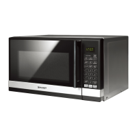
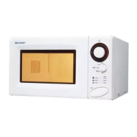
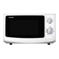
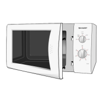
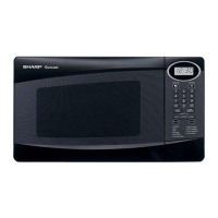
R-200BK
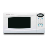
R-200BW
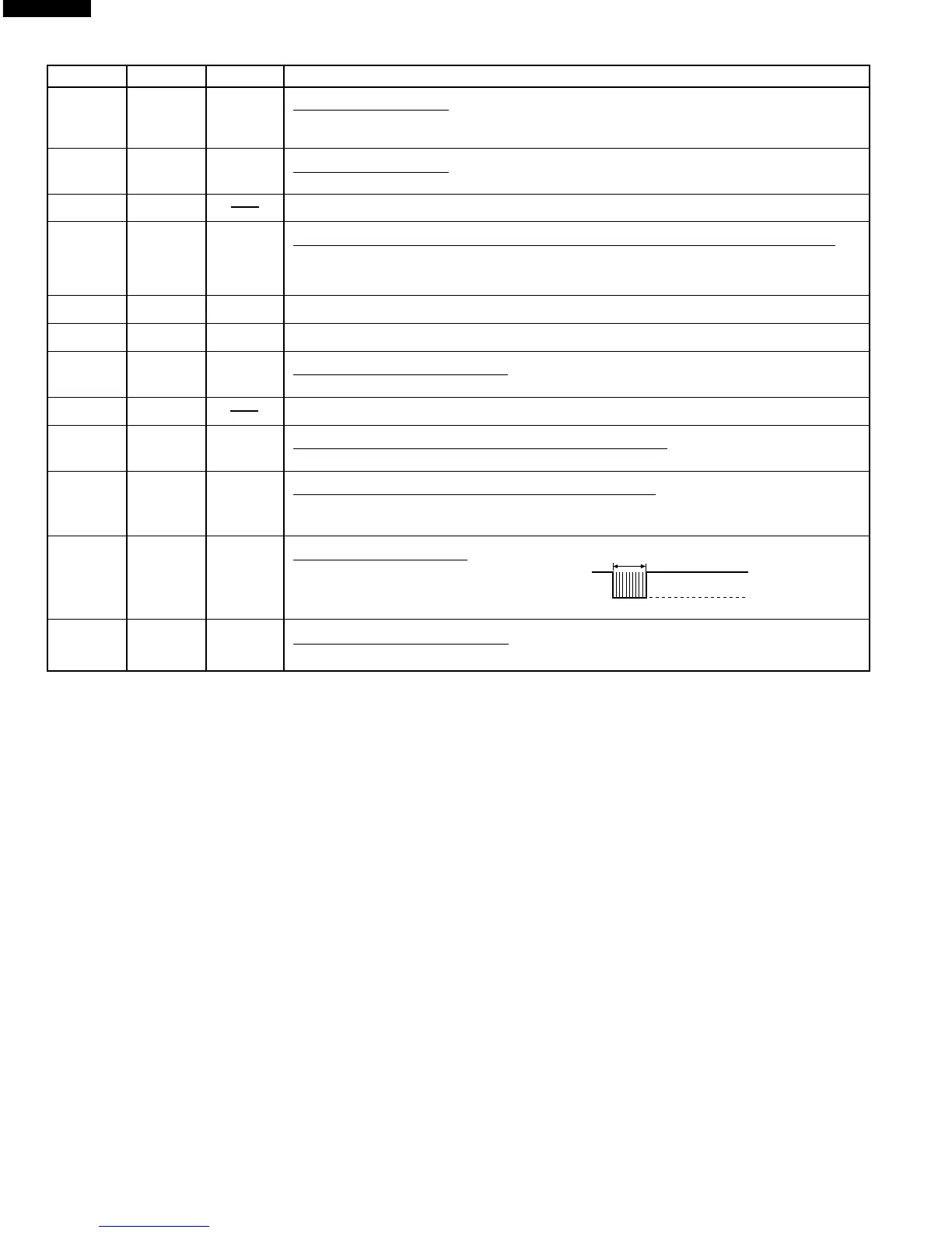
Pin No. Signal I/O Description
A
2.0 sec.
H : VC(+5V)
L : GND
22 D5 OUT Segment data signal.
Signal is input to the cathodes of the light-emitting diodes (LD1-LD4, LD6-LD9, LD11-
LD14, LD16-LD18 and LD19).
23-25 D6-D7 OUT Segment data signal.
Signal is input to the cathodes of all light-emitting diodes (LD1-D20).
26 NC No connection terminal.
27 F0 IN Input signal which communicates the door open/close information to LSI.
Door closed; “L” level signal.
Door opened; “H” level signal.
28 F1 OUT Connected to CNTR.
29 F2 OUT Terminal not used.
30 F3 IN Signal coming from encoder.
Signal similar to INT. Pulse signals are input into F3.
31-32 NC No connection terminal.
33 XOUT OUT Internal clock oscillation frequency control output.
Output to control oscillation input of XOUT.
34 XIN IN Internal clock oscillation frequency input setting.
The internal clock frequency is set by inserting the ceramic filter oscillation circuit with
respect to XIN terminal.
35 CNTR OUT Signal to sound buzzer.
A: Completion sound.
36 VDD IN Power source voltage: +5.0V.
The power source voltage to drive the LSI is input to VDD terminal.