17
R-3A56
DESCRIPTION OF LSI
LSI(IZA593DR)
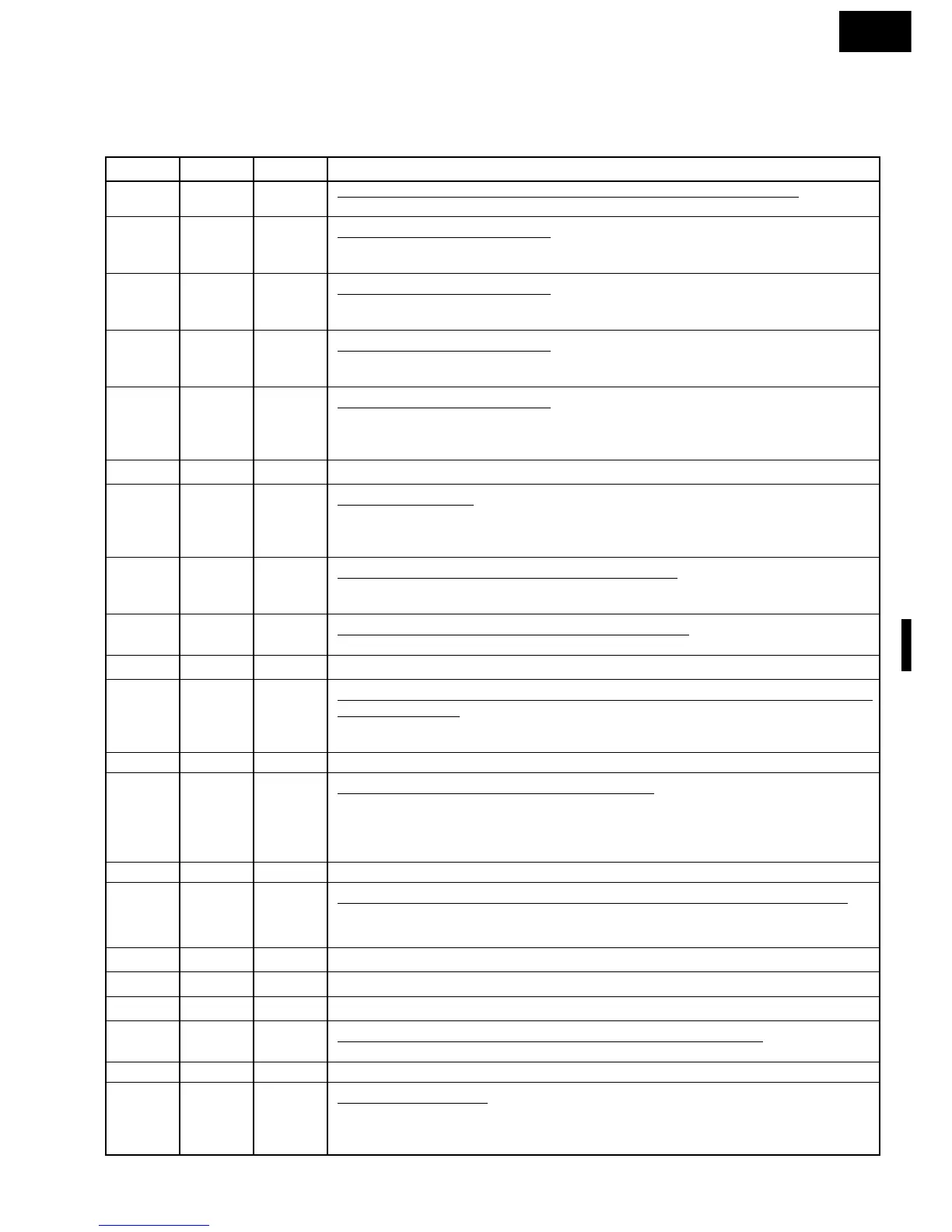
The I/O signal of the LSI(IZA593DR) is detailed in the following table.
Pin No. Signal I/O Description
1 Vdisp IN Anode (segment) of Fluorescent Display illumination voltage: -30V
Vp voltage of power source circuit input.
2R00IN Signal coming from touch key.
When either one of G12 line keys on key matrix is touched, a corresponding signal will
be input into R00.
3R01IN Signal coming from touch key.
When either one of G11 line keys on key matrix is touched, a corresponding signal will
be input into R01.
4R02IN Signal coming from touch key.
When either one of G10 line keys on key matrix is touched, a corresponding signal will
be input into R02.
5R03IN Signal coming from touch key.
When either one of G9 line keys on key matrix is touched, a corresponding signal out
of R20-R22, R10-R13 will be input into R03. When no key is touched, the signal is held
at "L" level.
6 TEST IN Connected to VC.
7 RESET IN Auto clear terminal.
Signal is input to reset the LSI to the initial state when power is supplied. Temporarily
set to "L" level the moment power is supplied, at this time the LSI is set. Thereafter set
at "H" level.
8 OSC1 IN Internal clock oscillation frequency input setting.
The internal clock frequency is set by inserting the ceramic filter oscillation circuit with
respect to OSC1 terminal.
9 OSC2 OUT Internal clock oscillation frequency control output.
Output to control oscillation input of OSC2.
10/11 GND/AVSS IN/IN Connected to VC.
12 AN0 OUT Oven lamp,turntable motor and cooling fan motor driving signal. (Square
Waveform : 50Hz)
To turn on and off the control relay. The pulse signal (50Hz) is delivered to the control
relay driving circuit and cook relay control circuit.
13 AN1 OUT Terminal not used.
14 AN2 OUT Magnetron high-voltage circuit driving signal.
To turn on and off the cook relay. In low operation, the signals holds "L" level during
microwave cooking and "H" level while not cooking. In other cooking modes (MED
HIGH, MED,MED LOW,LOW) the signal turns to "H" level and "L" level in repetition
according to the power level.
15 AN3 OUT Terminal not used.
16 AN4 IN Input signal which communicates the door open/close information to LSI.
Door closed; "H" level signal.
Door opened; "L" level signal.
17 AN5 IN Terminal to change cooking constant.
18-19 AN6-AN7 IN Connected to VC.
20/21 AVCC/VCC IN/IN Connected to GND.
22 INT0 IN Signal synchronized with commercial source freqency(50Hz).
This is basic timing for time processing of LSI.
23 D1 OUT Terminal not used.
24 D2 OUT Digit selection signal.
Refer to the touch control panel circuit about the relation between signals and digits.
Normally, one pulse is output in every synchronized signal period, and input to the grid
of the fluorescent display.