TEST PROCEDURES
PROCEDURE
LETTER
COMPONENT TEST
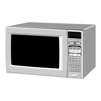
K TOUCH CONTROL PANEL ASSEMBLY TEST
The touch control panel consists of circuits including semiconductors such as LSI, ICs, etc. Therefore.
unlike conventional microwave ovens. proper maintenance cannot be performed with only a voltmeter
and ohmmeter.
In this service manual, the touch control panel assembly is divided into troubleshooting by unit re-
placement is described according to the symptoms indicated.
1. Key Unit.
The following symptoms indicate a defective key unit. Replace the key unit.
a) When touching the pads, a certain pad produces no signal at all
b) When touching a number pad, two figures or more are displayed.
c) When touching the pads, sometimes a pad produces no signal.
2. Control Unit
The following symptoms indicate a defective control unit. Replacethe control unit.
2-l In connection with pads.
a) When touching the pads, a certain group of pads do not produce a signal.
b) When touching the pads, no pads produce a signal.
2-2 In connection with indicators
a) At a certain digit, all or some segments do not light up.
b) At a certain digit, brightness is low.
cf Only one indicator does not light.
d) The corresponding segments of all digits do not light up: or they continue to light up.
ej Wrong figure appears.
.
f) A certain group of indicators do net light up.
g) The figure of all digits flicker.
2-3 C>ther possible troubles caused by defective control unit.
a\ Buzzer does not sound or continues to sound.
D,! Clock does not operate properly.
c! Cooking is not possible.
dr ?rooe: temperature measurement !s not obtained.
rqc;e
When defective components. the Control Unit or Key Unit are replaced, the defective par-! or
pans must be properly packed for return In the shipping carton, with its cushion material. in
which the new replacement part was shipped to you.
L KEY UNIT TEST
If tne display fails to clear when the STOP CLEAR pad is depressed. first verify the ribbon is makino
good contact. verify that thedoor sensing switchjstop switch) operates properly: that is the contacts are
closed when the door is closed and open when the door is open. If the door sensing switch(stop switch)
is good. disconnect the flat ribbon that connects the key unit to the control unit and make sure the door
sensing switch is closed(either close the door or short the stop switch connecter). Use the key unit
matrix indicated on the control panel schematic and place a jumper wire between the pins that corre-
spond to the STOP/CLEAR pad making momentary contact. If the control unit responds by clearing
with abeep. the key unit is faulty and must be replaced. If the control unit does not respond, it is faulty
and must be replaced. If a specific pad does not respond, the above method may be used f after
clearing the control unit) to determine if the control unit or key pad is at fault.
M
RELAY TEST
Remove the outer case and check voltage between Pin Nos. 7 and 9 of the g-pin connector (A) on the
control unit with an A.C. voltmeter.;
The meter should indicate 240 volts, if not check oven circuit.
Shut-off, Cook and Heater Relav Test
These relays are operated by D.C. voltage.
Check
voltage at the relay coil with a D.C. voltmeter during the microwave cooking or convection cooking
operatio
DC. voltage indicated
. . . . . . . . . . . . . . . . Defective
relay.
DC. voltage not indicated
. . . . . . . . ..Check diode which is connected to the relay coil. If diode is good,
control unit is defective.
20