A-9X55
ABSOLUTE HUMIDITY SENSOR CIRCUIT
(1) Structure of Absolute Humidity Sensor
The absolute humidity sensor includes two thermis-
tors as shown in the illustration. One thermistor is
housed in the closed vessel filled with dry air while
another in the open vessel. Each sensor is provided
with the protective cover made of metal mesh to be
protected from the external airflow.
Sensing part
(Open vessel)
Sensing part
(Closed vessel)
(2) Operational Principle of Absolute Humidity
Sensor
The figure below shows the basic structure of an
absolute humidity sensor. A bridge circuit is formed
by two thermistors and two resistors (Rl and R2;.
The output of the bridge circuit is to be amplified by
the operational amplifier.
Each thermistor is supplied with a current to keep it
heated at about 15OAKC (302 AKF), the resultant
heat is dissipated in the air and if the two thermistors
are placed in different humidity conditions they show
different degrees of heat conductivity leading to a
potential difference between them causing an output
voltage from the bridge.circuit, the intensity of which
is increased as the absolute humidity of the air in-
creases. Since the output is very minute, it is ampli-
fied by the operational amplifier.
S Thermtstor
C Thermistor
closed vessel
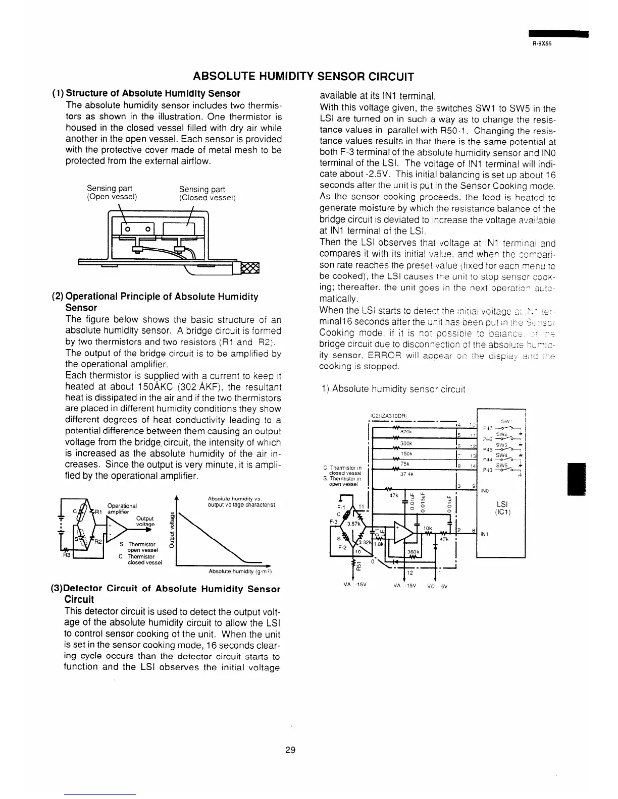
available at its IN1 terminal.
With this voltage given, the switches SW1 to SW5 in the
LSI are turned on in such a way as to change the resis-
tance values in parallel with R50-1. Changing the resis-
tance values results in that there is the same potential at
both F-3 terminal of the absolute humidity sensor and IN0
terminal of the LSI. The voltage of !Nl terminal will indi-
cate about -2.5V. This initial balancing is set up about 16
seconds after the unit is put in the Sensor Cooking mode.
As the sensor cooking proceeds. the food is heated ic
generate moisture by which the resistance balance of the
bridge circuit is deviated to increase the voltage a!iailable
at IN1 terminal of the LSI.
Then the LSI observes that voltage at IN! termrnal and
compares it with its initial value. and when the zcmoar;-
son rate reaches the preset value (fixed for each menu :c
be cooked), the LSI causes the unit to stop senscr zocii-
ing; thereafter. the unit goes in the next ooera:!.~~ :sL!~:-
matically.
When the LSI starts to detect the ;ni:!ai voitage 2: .‘,- :E*
minall6 seconds after the tinit has beeri DC! in rP$ Se-SC,
Cookins mode, if it is ~:GI ~cssib!e ;s naia,!n,z:, ~c -4
bridge circuit due to diseonnecticn of the absoi~:r “;mx-
ity sensor. ERROR will apoear o,~ :he dispiai z:,;~c ‘:~e
cooking is stooped.
1) Absolute humidity senscr circuit
(3)Detector Circuit of Absolute Humidity Sensor
Circuit
VA -15V
VA ‘-19’
VC -5v
This detector circuit is used to detect the output volt-
age of the absolute humidity circuit to allow the LSI
to control sensor cooking of the unit. When the unit
is set in the sensor cooking mode, 16 seconds clear-
ing cycle occurs than the detector circuit starts to
function and the LSI observes the initial voltage
29