EasyManua.ls Logo

Sharp SA-155H - User Manual

Sharp SA-155H
19 pages
To Next Page IconTo Next Page
Loading...
SA-155H/HB/E
SHARP
SERVICE
MANUAL
/SERVICE-ANLEITUNG/
MANUEL
DE
SERVICE
$8380SA-155H/
SA-155H
SA-155HB
SA-155E
PHOTO:
SA-155H
@
In
the
interests
of
user-safety
the
set
should
be
restored
to
its
original
condition
and
only
parts
identical
to
those
specified
be
used.
e
Im
Interesse
der
Benutzer-Sicherheit
sollte
dieses
Geraét
wieder
auf
seinen
urspriinglichen
Zustand
eingestellt
und
nur
die
vorgeschriebe-
nen
Teile
verwendet
werden.
@
Dans
|’inérét
de
la
sécurité
de
!'utilisateur,
l'appareil
devra
étre
reconstitué
dans
sa
condition
premiére
et
seules
des
piéces
identiques
a
celles
spécifiées,
doivent
étre
utilisées.
©
INDEX
TO
CONTENTS
SPECIFICATIONS
ccc
eo
sek
i
ee
See
we
Sw
es
2,3
NOTES
ON
SCHEMATIC
DIAGRAM..............005
15
VOLTAGE
SELECTOR
ADJUSTMENT
............0.8.
2,3
CABINET
EXPLODED
VIEW
............0...
0005
16,17
NAMES
OF
PARTS
........-.
0002
eee
eee
een
eee
4,5
CAUTION
(UK
ONLY)
..........
2.000.
eee
eee
eee
18
DISASSEMBEY’®
3e-i-6
ao
oe
el
8
GS
ee
ee
ee
ees
4,5
PACKING
METHOD
(UK
ONLY)............0.0
00008
18
DIAL
CORD
STRINGING
........
0.2.0.0
eee
ee
eee
6
EQUIVALENT
CIRCUIT
(BLOCK
DIAGRAM)
OF
IC......
19
ADJUSTMENT
OF
TUNER
CIRCUIT
.............
7~10
TYPES
OF
TRANSISTOR
AND
LED
.............6..
20
SCHEMATIC
DIAGRAM........
2.0.2.0
000+
eee
eae
11,12
REPLACEMENT
PARTS
LIST.............200-
21~
26
WIRING
SIDE
OF
P.W.
BOARD
.............+8-
13,
14
©)
INHALTSVERZEICHNIS
TECHNISCHE
DATEN.........
Cael
da
(sts
On ak
ah
Zo
Saal
Sas
TSB
2,3
VERDRAHTUNGSSEITE
DER
LEITERPLATTE.......
13,
14
EINSTELLUNG
DES
SPANNUNGSWAHLERS
..........
2,3
ANMERKUNGEN
ZUM
SCHEMATISCHEN
SCHALTPLAN
...
15
BEZEICHNUNG
DER
TEILE..............2.00000-
4,5
EXPLOSIONS
DARSTELLUNG
DES
GEHAUSES
......
16,17
ZER
LE
GEN
oc
eiiscs
eek
oa
ha
eR
eB
Je
a
A
4,5
ERSATZSCHALTKREIS
(BLOCKSCHALTPLAN)
SKALENSCHNURSPANNUNG
...........0
0000
ee
eee
6
DES
INTEGRIERTEN
SCHALTKREISES
.............
19
EINSTELLUNG
DES
TUNER-KREISES
............
7~10
TRANSISTOREN-UND
LEUCHTDIODENTYPEN..........
20
SCHEMATISCHER
SCHALTPLAN...........0..2.008
11,12
ERSATZTEILLISTE
...........
0.000
ee
eee
21
~
26
®)
TABLE
DES
MATIERES
CARACTERISTIQUES
nth
ada
Sh
AE
Me
ese
aoa
ed:
to
ee)
aca
na
eset
Seas,
GS
2,3
REMARQUES
CONCERNANT
LE
DIAGRAMME
REGLAGE
DU
SELECTEUR
DE
TENSION
...........
2,3
SCHEMATIQUE
|
Stas
Sy
tae
aatalytg.
abunee
aahaah
tel,
Ny
ore
Roa
ig
SD,
ves
ab,
Mein
cad
cae,
Faget
15
NOMENCLATURE
Seis
ad
Manto
ahve
aN
ep
oig:
A
wee
aes
Soe)
Sere
ye
4,5
VUE
EN
ECLATE
DU
COFFRET
...............
16,
17
DEMONTAGE
..........
0.2
ce
eee
een nee
e
een
nee
4,5
CIRCUITS
EQUIVALENTS
(DIAGRAMME
SYNOPTIQUE)
PASSAGE
DU
FIL
DU
CADRAN................004
6
PO
hy
ek)
a
eh
eA
a
ee
Ok
RS
BOK
CORRS
19
REGLAGE
DU
CIRCUIT
DU
TUNER..............
7a10
TYPES
DE
TRANSISTOR
ET
REDS:
ee
2asci
eal
ad
oc
Bad
a
20
DIAGRAMME
SCHEMATIQUE.........
eee
ae
11,12
LISTE
DES
PIECES
DE
RECHANGE
.............
21426
COTE
CABLAGE
DE LA
PLAQUETTE
DE
MONTAGE
IMPR
IME
oo,
5240
occa
es
ae
a
A
ec
Re
13,
14
SHARP
CORPORATION
os4
Question and Answer IconNeed help?

Do you have a question about the Sharp SA-155H and is the answer not in the manual?

Sharp SA-155H Specifications

General IconGeneral
Power output15 watts per channel into 8Ω (stereo)
Frequency response20Hz to 20kHz
Signal to noise ratio70dB (MM), 80dB (line)
Output150mV (line)
Tuning rangeFM: 88-108 MHz
Input sensitivity2.5mV (MM), 150mV (line)

Summary

Specifications

General Description

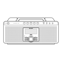
General overview of the unit's primary characteristics and power source.

Amplifier Section

Details on the amplifier's output power, frequency response, and input specifications.

Tuner Section

Technical specifications for FM and MW/LW tuning, including frequency coverage and sensitivity.

Voltage Selector Adjustment

Voltage Selector Adjustment (SA-155 H;HB)

Instructions for adjusting the voltage selector on the rear of the unit.

Names of Parts

Front Panel Components

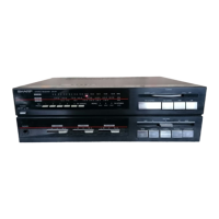
Identifies and lists parts on the front panel of the unit.

Rear Panel and Internal Connectors

Lists parts located on the rear panel and internal connectors.

Disassembly Procedures

Disassembly Cautions

Important safety and handling precautions to follow before and during disassembly.

Cabinet Removal

Step-by-step guide for removing the unit's outer cabinet.

Front Panel Removal

Instructions for safely removing the front panel assembly.

Bottom Plate Removal

Steps for detaching the bottom plate of the unit.

Dial Cord Stringing

Dial Cord Stringing Procedure

Detailed steps for correctly stringing the dial cord for the tuning mechanism.

Tuner Circuit Adjustments

FM IF;RF Adjustment

Procedures for adjusting the FM Intermediate Frequency (IF) and Radio Frequency (RF) circuits.

VCO Frequency Adjustment

Steps for adjusting the Voltage Controlled Oscillator (VCO) frequency for FM reception.

FM Stereo Separation Adjustment

Procedure for optimizing stereo separation in FM reception.

MW;LW IF;RF Adjustment

MW IF;RF Adjustment

Steps for adjusting the Intermediate Frequency (IF) and Radio Frequency (RF) circuits for MW band.

LW IF;RF Adjustment

Steps for adjusting the Intermediate Frequency (IF) and Radio Frequency (RF) circuits for LW band.

Notes on Schematic Diagram

Schematic Diagram Symbols

Explanation of symbols used in schematic diagrams, including capacitor and resistor notations.

Voltage Measurement Conventions

Details on how voltages are measured and indicated in the diagrams.

Model Specification Changes

Notice regarding potential changes to specifications or wiring diagrams without prior notice.

UK Specific Cautions

Wire Holder Replacement Caution

Warning about replacing wire holders to maintain original appearance and safety.

UK Packing Method

Packing Accessories and Case

Details on accessories and packing materials for the UK market.

Switch Position Settings

Standard Switch and Knob Settings

Specifies the default positions for all switches and knobs before operation.

Replacement Parts List

How to Order Replacement Parts

Instructions on how to provide necessary information for prompt and correct order fulfillment.

Important Parts for Safety

Highlights parts critical for maintaining the set's safety and performance, requiring specific replacements.

Resistor Notation

Explains the symbols K and M used to differentiate resistor units and the meaning of "Fusible".

Related product manuals