EasyManua.ls Logo

Sharp VC-H992U User Manual

Sharp VC-H992U
96 pages
To Next Page IconTo Next Page
Page #1 background imageLoading...
Page #1 background image
1
VC-A592U/A593U
VC-A5933U/H992U
VC-H993U/H994U
S39D7VC-A592U
SERVICE MANUAL
This document has been published to be used for
after sales service only.
The contents are subject to change without notice.
SHARP CORPORATION
In the interests of user-safety (Required by safety regula-
tions in some countries) the set should be restored to its
original condition and only parts identical to those specified
be used.
VIDEO CASSETTE RECORDER
SERVICE MANUAL
MODELS VC-A592U/A593U/A5933U/H992U/H993U/H994U
VIDEO CASSETTE RECORDER
VC-A592U/A593U
VC-A5933U/H992U
VC-H993U/H994U
Page
1. GENERAL INFORMATION .............................. 5
1-1 FEATURES .................................................5
1-2 SPECIFICATIONS ..................................... 5
1-3 LOCATION OF MAJOR COMPONENTS
AND CONTROL ......................................... 6
2. DISASSEMBLY AND REASSEMBLY .............. 7
2-1 DISASSEMBLY OF MAJOR BLOCKS ....... 7
2-2 DISASSEMBLING THE MECHANISM/
MAIN PWB ASSEMBLY............................. 8
2-3 CARES WHEN REASSEMBLING.............. 9
3. FUNCTION OF MAJOR MECHANICAL
PARTS ............................................................10
4. ADJUSTMENT, REPLACEMENT AND
ASSEMBLY OF MECHANICAL UNITS .......... 12
4-1 MECHANISM CONFIRMATION
ADJUSTMENT JIG .................................. 12
5. ELECTRICAL ADJUSTMENT ........................ 31
5-1 ADJUSTMENT OF HEAD SWITCHING
POINT .......................................................32
Page
5-2 ADJUSTMENT OF FV (False Vertical Sync)
OF STILL PICTURE ................................. 32
5-3 CHECKING OF OFF TRACK ................... 32
5-4 ADJUSTMENT OF SIF-INPUT LEVEL .... 33
5-5 ADJUSTMENT OF STEREO
SEPARATION ...........................................33
6. MECHANISM OPERATION FLOWCHART
AND TROUBLESHOOTING GUIDE .............. 34
7. TROUBLESHOOTING ................................... 40
8. BLOCK DIAGRAM ..........................................52
9. SCHEMATIC DIAGRAM AND PWB FOIL
PATTERN .......................................................60
10.PARTS LIST....................................................79
11.EXPLODED VIEW OF MECHANICAL
PARTS ............................................................88
12.PACKING OF THE SET ................................. 94
CONTENTS
VC-A592U/H992U
VC-A593U/H993U
VC-A5933U
VC-H994U
VC-A593U/A5933U/H992U .............. Models for Canada
VC-A592U/A593U/H993U/H994U .... Models for U.S.A.
VC-A592U
VC-A593U
VC-A5933U
VC-H992U
VC-H993U
VC-H994U
MODELS
Question and Answer IconNeed help?

Do you have a question about the Sharp VC-H992U and is the answer not in the manual?

Sharp VC-H992U Specifications

General IconGeneral
BrandSharp
ModelVC-H992U
CategoryVCR
LanguageEnglish

Summary

GENERAL INFORMATION

FEATURES

Lists features for specific models and common features of the video cassette recorder.

SPECIFICATIONS

Details technical specifications like format, tape speed, power requirements, and dimensions.

LOCATION OF MAJOR COMPONENTS AND CONTROL

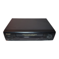
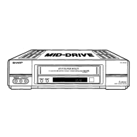
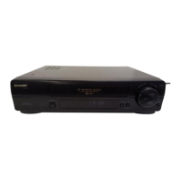
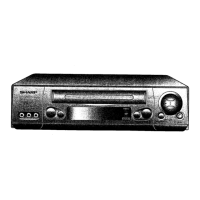
Identifies major components and controls on the front and rear of the VCR unit.

DISASSEMBLY AND REASSEMBLY

DISASSEMBLY OF MAJOR BLOCKS

Provides steps for removing major external blocks of the VCR.

DISASSEMBLING THE MECHANISM/MAIN PWB ASSEMBLY

Details the procedure for separating the mechanism from the main PWB.

CARES WHEN REASSEMBLING

Outlines important considerations and methods for reassembling.

FUNCTION OF MAJOR MECHANICAL PARTS

TOP VIEW

Identifies major mechanical parts from a top view with their functions.

ADJUSTMENT, REPLACEMENT AND ASSEMBLY OF MECHANICAL UNITS

MECHANISM CONFIRMATION ADJUSTMENT JIG

Lists special jigs required for mechanism adjustment and their purposes.

ELECTRICAL ADJUSTMENT

BEFORE THE ADJUSTMENT

Notes on checking the mechanism and components before starting electrical adjustments.

INSTRUMENTS REQUIRED

Lists necessary tools and test equipment for electrical adjustments.

SERVO CIRCUIT ADJUSTMENT

ADJUSTMENT OF HEAD SWITCHING POINT

Procedure to adjust the head switching point using an oscilloscope.

ADJUSTMENT OF FV (False Vertical Sync) OF STILL PICTURE

Method to minimize vertical jitter in still pictures using tracking controls.

CHECKING OF OFF TRACK

Procedure to check for off-track conditions and Hi-Fi sound issues.

MTS CIRCUIT ADJUSTMENT (HI-FI MODELS ONLY)

ADJUSTMENT OF SIF-INPUT LEVEL

Adjusts SIF input level for proper stereo separation.

ADJUSTMENT OF STEREO SEPARATION

Adjusts stereo separation for Hi-Fi audio.

MECHANISM OPERATION FLOWCHART AND TROUBLESHOOTING GUIDE

MECHANISM OPERATION FLOWCHART

Outlines the sequence of mechanism operations during cassette handling.

TROUBLESHOOTING

FF/REW FAILURE (NO TAPE WINDING)

Troubleshooting steps for failures when tape winding does not occur.

REC/PLAY FAILURE (MODE RELEASE)

Troubleshooting steps for failures in record/play modes or mode release.

BLOCK DIAGRAM

SYSTEM SERVO BLOCK DIAGRAM

Block diagram illustrating the servo system's interconnected components.

SCHEMATIC DIAGRAM AND PWB FOIL PATTERN

MAIN CIRCUIT(1)(VC-A592U/A593U/H994U)

Schematic diagram of the main circuit, part 1.

PARTS LIST

PARTS REPLACEMENT

General information on replacing parts with special safety characteristics.

HOW TO ORDER REPLACEMENT PARTS

Instructions for ordering replacement parts from Sharp.

HOW TO IDENTIFY CHIP TRANSISTORS AND DIODES BY ITS MARKING

Guide to identifying chip transistors and diodes by their markings.

EXPLODED VIEW OF MECHANICAL PARTS

MECHANISM CHASSIS PARTS

Exploded view of mechanical parts located on the mechanism chassis.

CASSETTE HOUSING CONTROL PARTS

Exploded view of the cassette housing control assembly parts.

CABINET PARTS

Exploded view of external cabinet components and related parts.

FRONT PANEL PARTS(VC-A592U/H992U)

Exploded view of front panel parts for specific models.

FRONT PANEL PARTS(VC-A593U/H993U)

Exploded view of front panel parts for specific models.

FRONT PANEL PARTS(VC-A5933U/H994U)

Exploded view of front panel parts for specific models.

PACKING OF THE SET

Setting position of the Knobs

Instructions for setting knobs and accessories during packing.

Related product manuals