1
VC-A592U/A593U
VC-A5933U/H992U
VC-H993U/H994U
S39D7VC-A592U
SERVICE MANUAL
This document has been published to be used for
after sales service only.
The contents are subject to change without notice.
SHARP CORPORATION
In the interests of user-safety (Required by safety regula-
tions in some countries) the set should be restored to its
original condition and only parts identical to those specified
be used.
VIDEO CASSETTE RECORDER
SERVICE MANUAL
MODELS VC-A592U/A593U/A5933U/H992U/H993U/H994U
VIDEO CASSETTE RECORDER
VC-A592U/A593U
VC-A5933U/H992U
VC-H993U/H994U
Page
1. GENERAL INFORMATION .............................. 5
1-1 FEATURES .................................................5
1-2 SPECIFICATIONS ..................................... 5
1-3 LOCATION OF MAJOR COMPONENTS
AND CONTROL ......................................... 6
2. DISASSEMBLY AND REASSEMBLY .............. 7
2-1 DISASSEMBLY OF MAJOR BLOCKS ....... 7
2-2 DISASSEMBLING THE MECHANISM/
MAIN PWB ASSEMBLY............................. 8
2-3 CARES WHEN REASSEMBLING.............. 9
3. FUNCTION OF MAJOR MECHANICAL
PARTS ............................................................10
4. ADJUSTMENT, REPLACEMENT AND
ASSEMBLY OF MECHANICAL UNITS .......... 12
4-1 MECHANISM CONFIRMATION
ADJUSTMENT JIG .................................. 12
5. ELECTRICAL ADJUSTMENT ........................ 31
5-1 ADJUSTMENT OF HEAD SWITCHING
POINT .......................................................32
Page
5-2 ADJUSTMENT OF FV (False Vertical Sync)
OF STILL PICTURE ................................. 32
5-3 CHECKING OF OFF TRACK ................... 32
5-4 ADJUSTMENT OF SIF-INPUT LEVEL .... 33
5-5 ADJUSTMENT OF STEREO
SEPARATION ...........................................33
6. MECHANISM OPERATION FLOWCHART
AND TROUBLESHOOTING GUIDE .............. 34
7. TROUBLESHOOTING ................................... 40
8. BLOCK DIAGRAM ..........................................52
9. SCHEMATIC DIAGRAM AND PWB FOIL
PATTERN .......................................................60
10.PARTS LIST....................................................79
11.EXPLODED VIEW OF MECHANICAL
PARTS ............................................................88
12.PACKING OF THE SET ................................. 94
CONTENTS
VC-A592U/H992U
VC-A593U/H993U
VC-A5933U
VC-H994U
VC-A593U/A5933U/H992U .............. Models for Canada
VC-A592U/A593U/H993U/H994U .... Models for U.S.A.
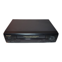
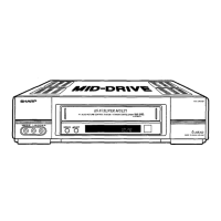
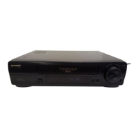
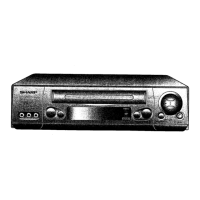
VC-A592U
VC-A593U
VC-A5933U
VC-H992U
VC-H993U
VC-H994U
MODELS