VL-E39S
3
m4.
REPLACEMENT OF CCD SENSOR
3-4-1. BEFORE
REPLACEMENT
1) The CCO image sensor is more sensitive to electrostatic
breakage than C-MOS LSI. Therefore sufficient means to
prevent electrostatic damage must be taken when it is re-
placed.
" Ground the soldering iron.
" Ground also the human body, using the wrist strap(through an
1 Mohm resistor).
e Until the CCOsensor is mounted on the PWB, fit it to the
conductive sponge, and short-circuit the foot lead.
2) Take utmost care so that the surface glass of CCO sensor and
optical filter are not contaminated and damaged. If
any
con-
tamination is found, for example fingerprint, wipe it off with
silicon paper or clean chamois skin.
3) When replacing the CCO sensor, use the antistaic grounded
soldring iron, and perform quickly soldering.
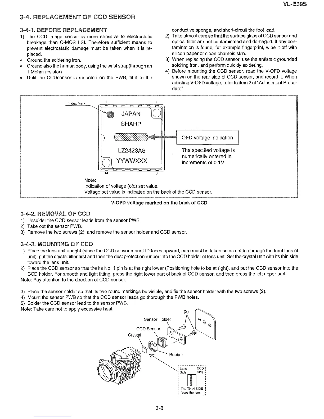
4) Before mounting the CCO sensor, read the V-OFO voltage
shown on the rear side of CCO sensor, and record it. When
adjisting V-OFO voltage, refer to item
2 of "Adjustment Proce-
dure".
Index Mark
JAPAN
SHARP
7
o
OFO
voltage
indication
o
LZ2423A6
YYWWXXX
The
specified
voltage
is
numerically
entered
in
increments
of 0.1V.
14
8
Note:
Indication of voltage (ofd) set value.
Voltage set value is indicated on the back of the CCO sensor.
V-OFD voltage marked on
the
back
of CCD
3-4-2.
REMOVAL
OF CCO
1) Unsolder the CCO sensor leads from the sensor PWB.
2) Take out the sensor PWB.
3) Remove the two screws (2), and remove the sensor holder and CCO sensor.
3-4-3. MOUNTING OF ceo
1) Place the lens unit upright (since the CCO sensor mount 10faces upward, care must be taken so as not to damage the front lens of
unit), put the crystal filter first and then the dust protection rubber into the CCO holder of lens unit. Set the crystal unit with its thin side
toward the lens unit.
2) Place the CCO sensor so that the its
NO.1 pin is at the right lower (Positioning hole to be at right), and put the CCO sensor into the
CCO holder. For smooth and tight fitting, press the right lower part of back of CCO sensor, and then press the left upper part.
Note: Pay attention to the direction of CCO sensor.
(2)
l)
Sensor
HOld~r
~
~ ~
CCD Sensor
C~~~~
~
-----
Rubber
------------
..
: Lens
CGo:
, Side
[[]
Side :
, ,
, ,
, ,
, ,
, ,
: The THIN SIDE :
:_
~a:~~~:
~e_n:
__
:
3) Place the sensor holder so that its two round markings be visible, and fix the sensor holder with the two screws (2).
4) Mount the sensor PWB so that the CCO sensor leads go thorough the PWB holes.
5) Solder the CCO sensor lead to the sensor PWB.
Note: Take care not to apply excessive heat.