4-24
VL-E610S/VL-E610H
VL-E660S/VL-E96E
VL-E98E
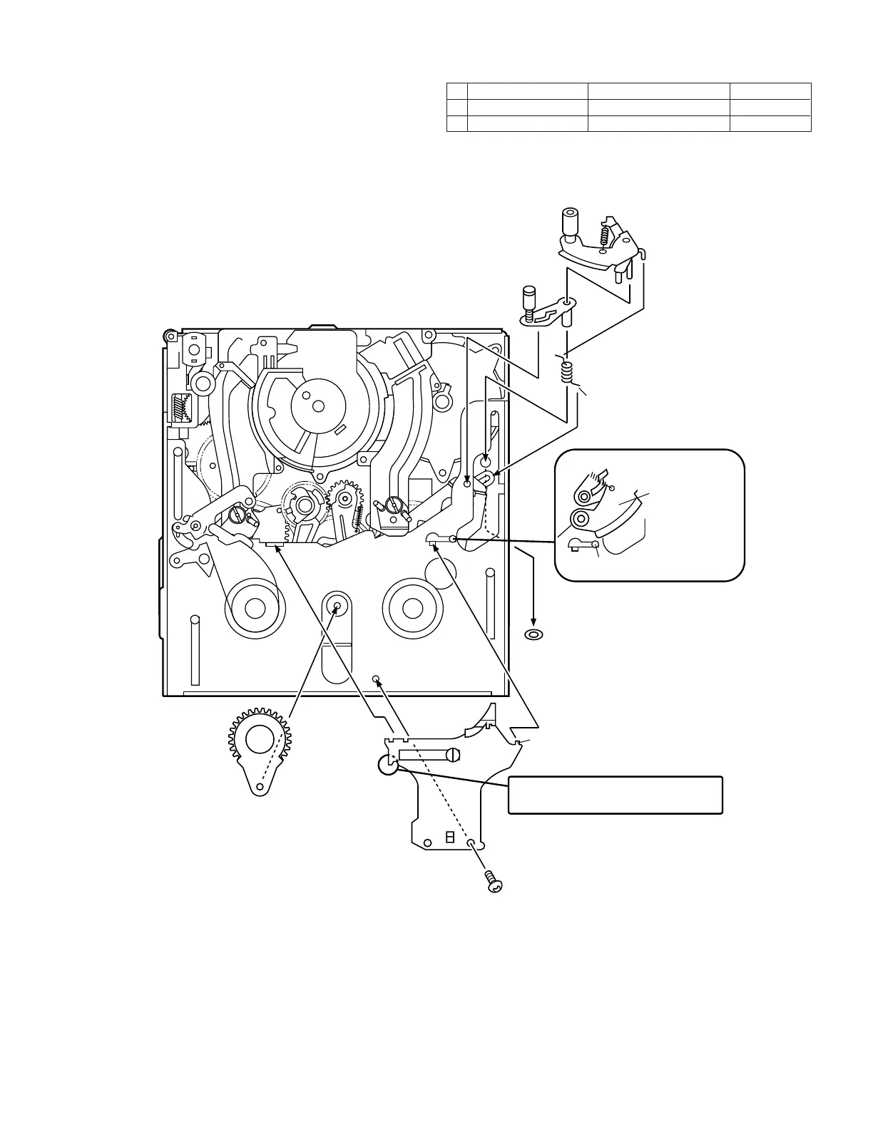
(12) Install in the following order: T guide lever spring, T guide lever, pinch lever.
(13) Install the swing arm.
(14) Install the right guide holder.
Take care not to bend the tension band
during assembly or disassembly.
Pinch lever
Tu guide lever
Tu guide lever SPR
Attach to hook
Attach to hook
Take care of position.
Pinch lever
Stopper
The pinch lever
is positioned on
the stopper.
Secure on back side
B
A
Claw
Claw
Swing arm
Item Tightening torque Quantity
A S tight M1.4 x 2.5 70mN·m 1
B CW ø0.8-ø3.0-t0.2 70mN·m 1