5-11
VL-E610S/VL-E610H
VL-E660S/VL-E96E
VL-E98E
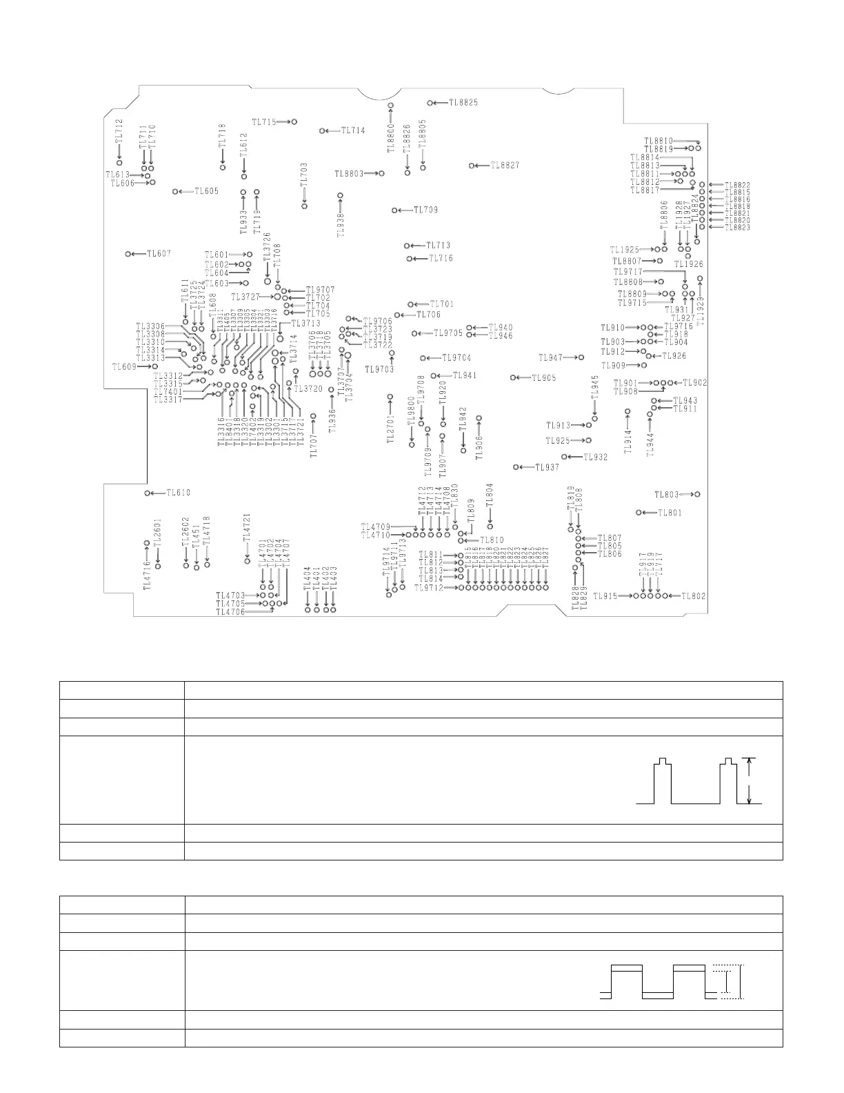
Measuring point TL817 (G-OUT)
Address 40
Mode VCR AV input
Adjusting method 1)Set the data of address 47 at the address 80.
2)Input white 100% as an AV input.
3)Connect TL805 to GND. (The 1H inversion stops.)
4)Connect 220 KΩ between TL803 and GND.
5)Seeing the waveform of TL817 (G-OUT), make an adjustment between
the white peak and the sync tip.
Adjustment standard
3.3V ± 0.1V
Remarks ———————
1. Contrast adjustment
Measuring point TL817 (G-OUT) TL816 (R-OUT)
Address 41
Mode VCR AV input
Adjusting method 1)AV input: Nonsignal.
2)TL817 (G-OUT): Oscilloscope CH1
TL816 (R-OUT): Oscilloscope CH2
3)Adjust P-P of TL816 becomes bigger 0.15V than TL817.
Adjustment standard
±0.1Vp-p
Remarks ———————
2. R-W/B adjustment
G R
5-1-7. Adjustment of LCD display circuit
Adjustment procedures and connections are the same as with the VCR section.