5-12
VL-E610S/VL-E610H
VL-E660S/VL-E96E
VL-E98E
Measuring point TL817 (G-OUT) TL818(B-OUT)
Address 42
Mode VCR AV input
Adjusting method 1)AV input: Nonsignal.
2)TL817 (G-OUT): Oscilloscope CH1
3)
TL818 (B-OUT): Oscilloscope CH2
4)Adjust P-P of TL818 become bigger 0.1V than TL817.
Adjustment standard
±0.1Vp-p
Remarks ———————
3. B-W/B adjustment
4. VCO adjustment
Measuring point TL808
Address 43
Mode VCR AV input
Adjusting method 1)AV input : NON Signal
2)Connect the frequency counter to TL808, and adjust the frequency.
Adjustment standard
15.625kHz ± 100Hz
Remarks ———————
Measuring point TL808
Address 44
Mode VCR AV input
Adjusting method 1)Input the white 100% signal as an AV input.
2)Connect the oscilloscope to TL808, and adjust the pulse width.
Adjustment standard
3.9µsec
± 0.15µsec
Remarks ———————
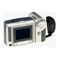
5. H-position adjustment
6. COMMON PULSE adjustment
Measuring point TL821
Address 22
Mode VCR AV input
Adjusting method 1)Set the data of address 47 at the address 80.
2)Input the white 100% signal as an AV input.
3)Connect the oscilloscope to TL821, and adjust the pulse width.
Adjustment standard
6.8Vp-p ± 0.1Vp-p
Remarks ———————
7. Burst phase adjustment
Measuring point TL818
Address 49
Mode VCR AV input
Adjusting method 1)Input the monochrome signal (R) to the AV input.
2)Connect TL805 to GND. (1H inversion stop)
3)Set the data of address 48 to 30.
4)Minimize the signal level difference every 1H.
Adjustment standard
± 400mV
Remarks ———————