VL-E610S/VL-E610H
VL-E660S/VL-E96E
VL-E98E
3-1
3. DISASSEMBLY OF THE SET
3-1. Removal of the camera section
Note:
Before removing the cabinet, turn off the power supply, and ascertain that the battery has been removed.
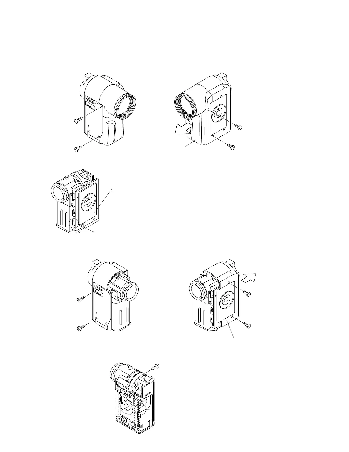
1. Remove one screw ((d)XiPSF20P04000), one screw ((b)LX-HZ0018TAFF), two screws ((a)LX-HZ0018TAFN), and pull
out the camera front cabinet (1).
(1)
Camera front cabinet
(a)
(d)
(b)
(a)
Pull out
2.Remove the connector (1 pc.).
Tilt frame C
Connector
Note:
When assembling the camera rear cabinet, lay the FPC
between the camera shield case and the tilt frame C, and
insert it into the connector.
* Remove the Camera rear cabinet, after removing the
connector.
4. Firstly, remove the CCD connector from the Camera PWB, then remove one screw ((c)LX-HZ0045TAFN), the reverse
side in this figure (Not remove the lens holder in this section).
CCD connector
3.Remove one screw ((b)LX-HZ0018TAFF), one screw ((d)XiPSF20P04000) and two screws ((a)LX-HZ0018TAFN) and
pull out the camera rear cabinet (2) backwards.
(b)
(2)
Camera rear cabinet
(a)
(a)
Pull out
(d)
(c)