3
VL-E780U
VL-E785U
VL-E785T
4. DISASSEMBLY OF THE SET
4-2. Disassembly of the VCR main body
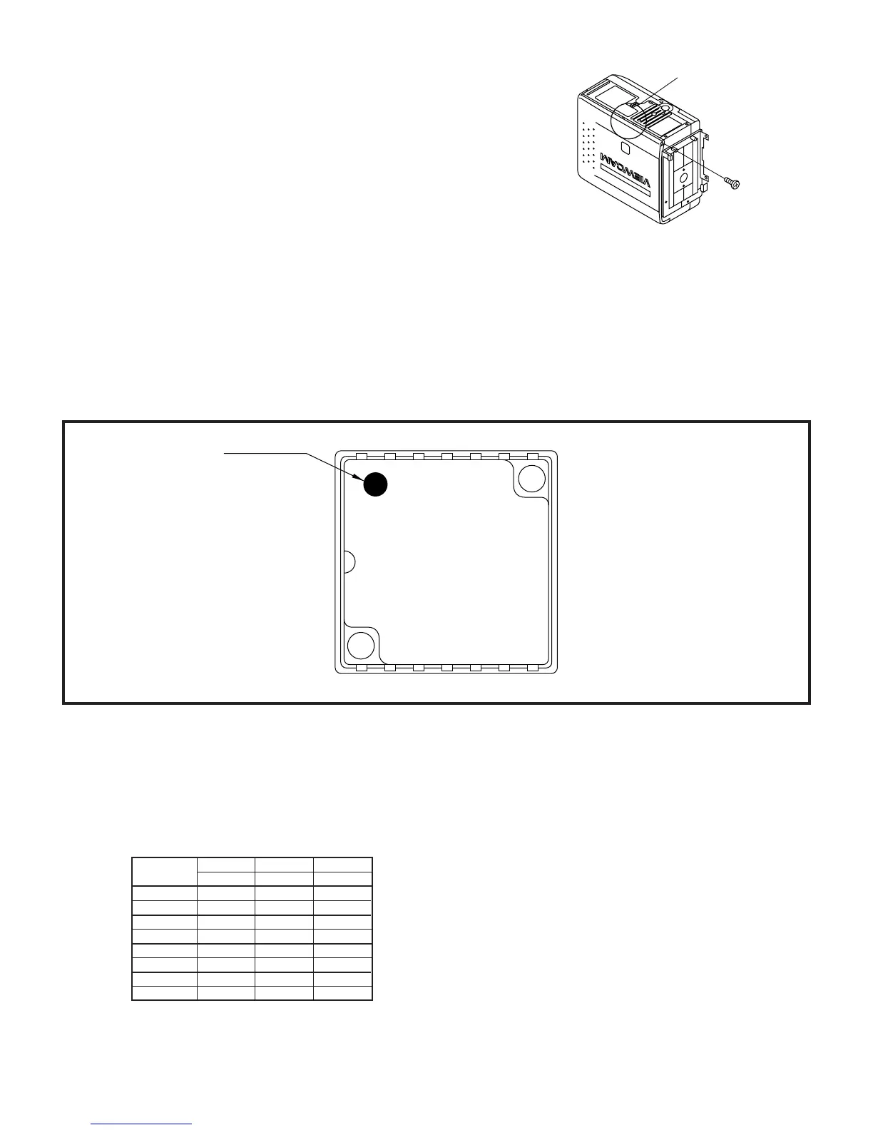
1. Removal of the VCR lid shaft
(1)Remove one screw ((j)LX-HZ0063TAFC).
Area A
(j)
4-3. REPLACEMENT OF CCD SENSOR
4-3-1. BEFORE REPLACEMENT
1) The CCD image sensor is more sensitive to electrostatic breakage than C-MOS LSI. Therefore sufficient means to
prevent electrostatic damage must be taken when it is replaced.
• Ground the soldering iron.
• Ground also the human body, using the wrist strap(through an 1 Mohm resistor).
• Until the CCDsensor is mounted on the PWB, fit it to the conductive sponge, and short-circuit the foot lead.
2) Take utmost care so that the surface glass of CCD sensor and optical filter are not contaminated and damaged. If any
contamination is found, for example fingerprint, wipe it off with silicon paper or clean chamois skin.
3) When replacing the CCD sensor, use the antistaic grounded soldring iron, and perform quickly soldering.
JAPAN
SHARP
Index Mark
LZ2413H5
YYWWXXX
17
14 8
4-4. INITIAL SETTING OF E
2
PROM IC
4-4-2. IC702 (E
2
PROM)
When the IC702 has been replaced, make the following settings and adjustments.
1. Remove the backup battery (CR2025)
2. Turn power switch to CAMERA
3. Setting up the V ADJ mode as follows.
* After press the CONTINUE key, press the VCR ADJ key on service remote control (RRMCG0033TASA).
E780U E785U E785T
address data data data
03 F8 FA FE
0B 07 05 01
01 00 00 00
09 FF FF FF
04 00 00 00
0C FF FF FF
02 01 01 07
0A FE FE F8