VL-E780U
VL-E785U
VL-E785T
4
5. MECHANISM ADJUSTMENT
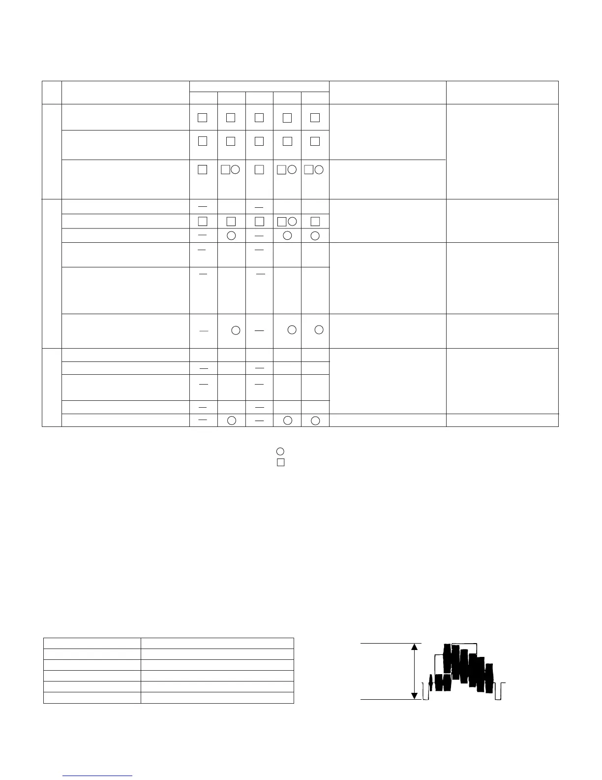
5-2. Items and timings of inspection and maintenance
5-2-1. Inspection and maintenance list
Checking/Maintenance point
Tape travelling route
(Refer to Section)
Remarks
Rollers
• If abnormal rotation or
deflection (significant) is
found, replace the roller.
Other than rollers
• Clean the tape contact-
ing areas. Be sure to
use the specified clean-
ing agent.
Possible symptom
encountered
• Lateral noise
• Unclean head
• Screen shaking
Usage time (hrs.)
500 1,000 1,500 2,000 3,000
Drum (Refer to Section)
• Improper S/N ratio
• No color appears.
Video head
Tape travel system
Timing belt
Pinch roller
Capstan D.D. motor
• Tape does not run.
• Tape slackens.
• Screen shakes.
★★★
• Replace if failure is
found.
Relay Pulle shaft
Pulle gear shaft
Drive gear shaft
∆∆∆
∆∆∆
• Abnormal sound
• Apply oil.
(Oil: )
Note:
After oil is applied to the
drive gear shaft, slightly
wipe it off with swab.
Loading motor
• Replace if failure (abnor-
mal sound) is detected.
• Not ejectable
• The specific mode can-
not be set.
Driving system
★★★
Abnormal sound
PB/VS-REW take-up torque
PB/VS-REW back tension
torque
Tu brake
★★★★★
★★★
★★★
★★★
HC (Head Cleaner)
Performance check
• If conformance to the
standard is not ensured,
replace part.
Oil:
Grease: MORYCOAT YM-103/X5-6020
Screw locking agent: THERE BOND 1401B
Cleaning liquid: Industrial-use ethyl alcohol
: Replace.
: Clean.
∆ : Apply oil.
★ : Check.
5-4. ADJUSTMENT OF MECHANISM TAPE TRAVEL SYSTEM
5-4-3. Adjusting the Si roller height
(2) Adjusting the Si roller
1 Playback the tape such as to set the V/SR mode.
6. ADJUSTMENT OF VCR
6-1. ADJUSTMENT OF VCR SECTION
6-1-5. Y/C circuit adjustment method
2. Adjustment of input Y level
Measuring instrument Oscilloscope
Mode VCR STOP
Input signal Color bar
Measuring point TL801
Adjustment address 32
Adjustment level 500 Vp-p ± 20 mVp-p