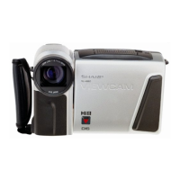
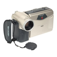
VL-H860U
VL-H880U
VL-H870U
VL-H875U
VL-H890U
6
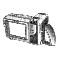
4. DISASSEMBLY OF THE SET
4-1. DISASSEMBLY OF THE VCR PARTS
<8. Removal of LCD Unit>
Configuration
<Note: The entries of list> 1. Name 2. Part No. 3. Code
4. Note * Model, Uses Remarks
1. Extension Cable LCD~
VCR (24pin)
2. QCNW-1382TAZZ
3. BD
1. Extension Cable
Inverter~VCR (7pin
)
2. QCNW-1265TAZZ
3. AX
1. Extension Cable
Camera~VCR (18pin)
2. QCNW-1270TAZZ
3. AY
1. Extension Cable
Camera~VCR (19pin)
2. QCNW-1381TAZZ
3. AX
1. Extension Cable
MECHA~VCR (70pin)
2. QCNW-1534TAZZ
3. BS
12345
6
7
8
1. Service remote control
2.
RRMCG0033TASA
3. BT
1. Operation Unit
2.
QSW-Z0287TAZZ
3.
AW
1. DC-IN Jack Unit
2.
QJAKZ0069TAZZ
3. AK
1. AV Jack Unit
2. QJAKZ0070TAZZ
3. AX
1. Connector fitting and
withdrawing extractor
1. Connector fitting and
withdrawing tweezers
2. 9EQPiNSET06GE
3. BR
insulating sleeve
(C)LCD Panel
(D)LCD Holder A
(F) Prism Sheet
(G)Diffusion Sheet
(H)Light Guide Plate
(I) Reflection Polarizing Sheet
(J) Lamp Inverter
(K) LCD Holding Sheet
6-3. ADJUSTMENT OF VCR SECTION
6-3-2. Servicing the VCR section Adjustment
6-3-2-1. Typical connections
<Extension Cable etc.>
6. ADJUSTMENT OF VCR AND CAMERA
6-1. INITIAL SETTING OF E
2
PROM IC
6-1-2. IC703 (E
2
PROM)
When the IC703 has been replaced, make the following settings and
adjustments.
3. Setting up the V ADJ mode as follows.
* After press the CONTINUE key, press the VCR ADJ key on service
remote control (RRMCG0033TASA).
H860U H880U
address data data
03 (Specificaton code) 4D 4D
02 (Country code) 01 01
(I)
(3)
(a)
(D)
(J)
(1)
(K)
(C)
(4)
(2)
(F)
(G)
(H)
``
``
` Refer to the item CABINET EXPLODED VIEW about other parts.
•At the time of removing from the LCD Holder A(D), and take off the hooks(1)(2pcs.).
•At the time of removing from the LCD Holder A(D), take off (K), remove the FPC from
the hooks(3)(2pcs.), disengage the claw(2), and slide the LCD Panel (C) in the (a)
direction to remove the LCD Holder A (D).
•At the time of removing from the LCD Holder A(D), remove the claws (4)(2pcs.).
· Alignment Tape
JiGWR5-5NSP (NTSC) ....Normal 8 TAPE (MONO)
JiGWR5-8NSE (NTSC) ...Hi8 TAPE (MONO)
* Y/C Audio Alignment
· Standard Tape
JiGWR5-9NS(NTSC)....... Hi8 TAPE (STEREO)