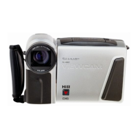
VL-H870U
VL-H875U
VL-H890U
6-1
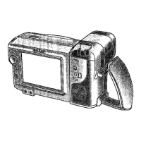
VL-H860S/H/VL-H870S
VL-H890S/VL-H94E
VL-H96E/VL-H960E
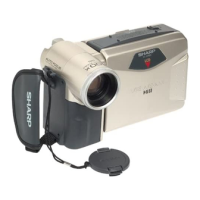
VL-H860S/H/VL-H870S
VL-H890S/VL-H94E
VL-H96E/VL-H960E
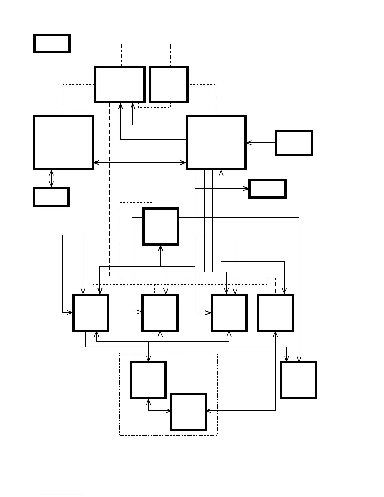
* On this model, all the circuits of the VCR and camera sections are controlled by IC704 and IC501.
1) IC501 and IC401 are controlled with the serial data from IC704.
2) IC703 is a memory that serves to store the adjustment data of the VCR section.
3) IC2 is a memory that serves to store the adjustment data of the camera section.
4) The other circuits and ICs are under the L/H level or the PWM control.
6. SYSTEM BLOCK DIAGRAMS
BATTERY
NONREGE
IC900
IC501
IC2
IC401 IC601 IC2702
IC800
IC4701 & IC4702
D/A
IC704
IC703
POWER (CAMERA)
E
2
PROM
E
2
PROM
SERIAL BUS
SERIAL BUS
Y/C AUDIO ATF
SERVO
CIRCUIT
LCD
CIRCUIT
H/A
UNIT
MECHA-
NISM
MECHA-
CHASSIS
POWER (SIGNAL)
POWER (MOTOR)
SYSTEM SERVO
CONTROLLER
KEY
3.3V
Converter
POWER (AT 3.3V)
POWER (SYS 3.3V)
DC/DC
CONVERTOR
CAMERA
MICRO-
COMPUTER
IC701 & Q701