– 9 –
XL-505/505C,CP-505B
MECHANISM SECTION
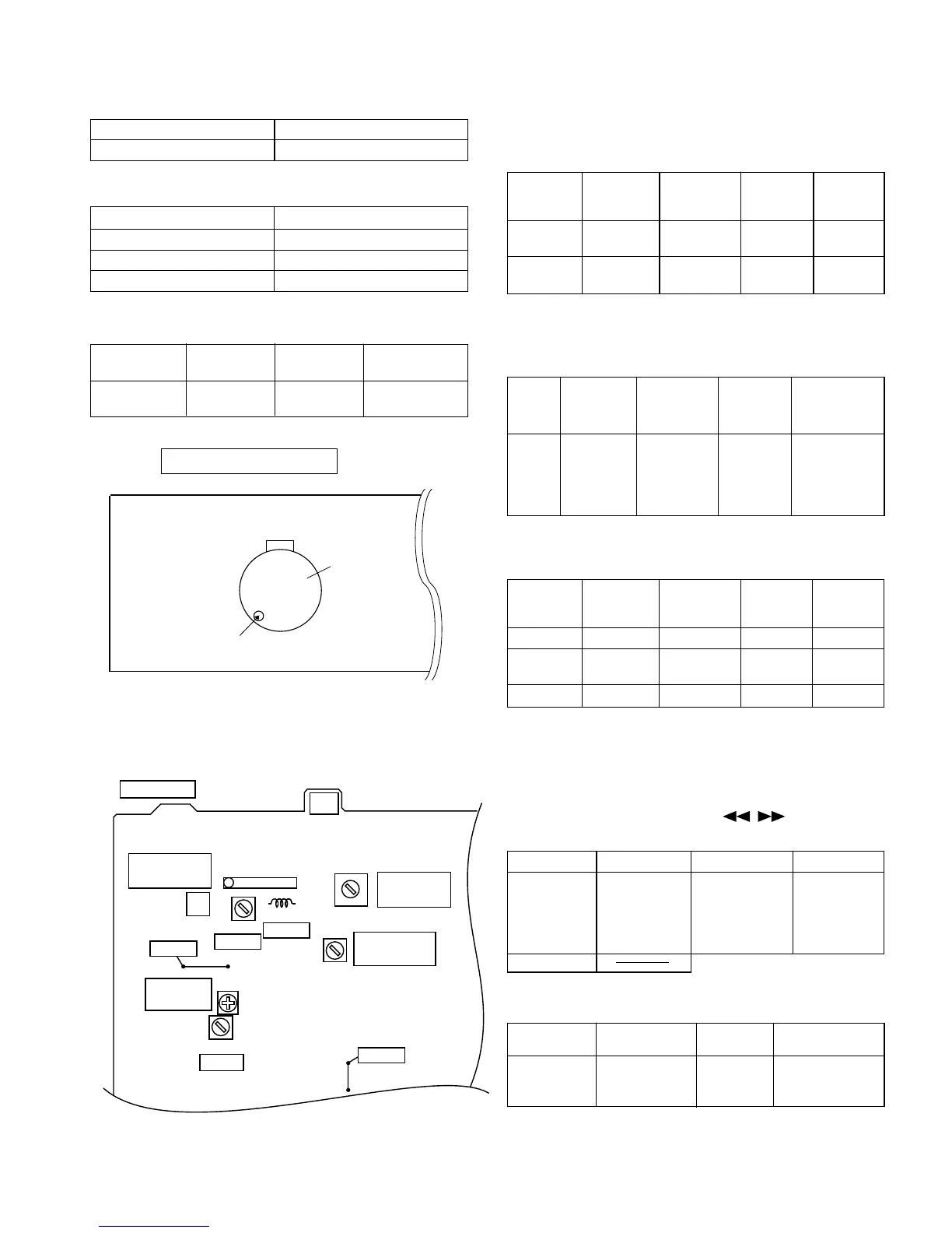
• Driving Force Check
Torque Meter
Specified Value
Play: TW-2412 Over 80 g
• Torque Check
Torque Meter
Play: TW-2111 30 to 70 g. cm
Fast forward: TW-2231 50 to 140 g.cm
Rewind: TW-2231 50 to 140 g.cm
Specified
Value
Adjusting
Point
Instrument
Connection
Test Tape
MTT-111 In Motor 3,000 ± Headphones
90 Hz
ADJUSTMENT
Specified Value
• Tape Speed
fL: Low-range frequency
fH: High-renge frequency
IF 450 kHz 1,720 kHz T351 *1
Band — 530 kHz (fL): T306 *2
Coverage 1.1 ± 0.1 V
Tracking 990 kHz 990 kHz (fL): T302 *1
Test Stage
Frequency Frequency
Display
Setting/
Adjusting
Parts
Instrument
Connection
Adjusting
Parts
Instrument
Connection
Display
Frequency
98.00 MHz 98.00 MHz VR351*1 Input: SO301
(25 dBµV) Output: Speaker
Terminal
Figure 9-1 ADJUSTMENT POINT
TUNER SECTION
TAPE MECHANISM
M901
Motor
Volume in motor
• FM RF
Signal generator: 1 kHz, 75 kHz dev., FM modulated
Band — 87.50 MHz (fL): L303 *1
Coverage 3.4 ± 0.1 V
RF 98.00 MHz 98.00 MHz L302 *2
(10~30 dB)
Test Stage Frequency
Frequency
Display
Setting/
Adjusting
Parts
Instrument
Connection
*1. Input: Antenna, Output: TP301
*2. Input: Antenna, Output: Speaker Terminal
• Detection
Signal generator: 10.7 MHz, FM sweep generator
IF 10.7 MHz 98.00 MHz T304(Turn Input: Pin 1 of
the core of IC301
T304 fully Output: TP302
counter-
clockwise.
Test
Stage
Frequency Frequency
Display
Setting/
Adjusting
Parts
Instrument
Connection
*1. Input: Antenna, Output: Speaker Terminal
*2. Input: Input is not connected, Output: TP301
• Setting the Test Mode
Keeping the BAND button and MEMORY button pressed, turn
on POWER. Then, the frequency is initially set in the memory
as shown in Table. Call it with the , button to use it
for adjustment and check of tuner circuit.
Preset No.
FM
Preset No.
AM
1 87.50 MHz 6 530 kHz
2 108.00 MHz 7 1,720 kHz
3 98.00 MHz 8 990 kHz
4 90.00 MHz 9 600 kHz
5 106.00 MHz 10 1,400 kHz
11~40
• FM Mute Level
Signal generator: 1 kHz, 40 kHz dev., FM modulated
Adjust so that an output signal appears.
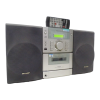
Figure 9-2 ADJUSTMENT POINTS
• AM IF/RF
Signal generator: 400 Hz, 30%, AM modulated
CNP301
ANTENNA
MAIN PWB
T302
IC301
L302
T304
L303
T306
T351
VR351
1
AM
TRACKING
FM BAND
COVERAGE
AM BAND
COVERAGE
FM IF
FM RF
FM MUTE
LEVEL
AM IF
TP301
TP302