XL-MP110H/MP110E
2 – 1
AudioXL-MP110H/MP110EService ManualXLMP110H/EMarketE
CHAPTER 2. ADJUSTMENTS
[1] ADJUSTMENT
1. MECHANISM SECTION
• Driving Force Check
• Torque Check
2. TUNER SECTION
fL: Low-range frequency
fH: High-range frequency
• AM IF/RF
Signal generator: 400 Hz, 30%, AM modulated
Notes:
1. Description of the "FM IF Adjustment" is not carried on this Manual.
It is because the IF coil in the FM front end section has been best
adjusted in the factory so that its further adjustment is not needed
at the field. When replacing the FM front end assembly, no adjust-
ment is needed either.
2. The parts in the FM front end section are prepared in a complete
unit, so you can't obtain each part individually.
• Tape Speed
3. CD SECTION
• Adjustment
Since this CD system incorporates the following automatic adjust-
ment functions, readjustment is not needed when replacing the
pickup. Therefore, different PWBs and pickups can be combined
freely.
Each time a disc is changed, these adjustments are performed
automatically. Therefore, playback of each disc can be performed
under optimum conditions.
Items adjusted automatically
1) Offset adjustment (The offset voltage between the head amplifier
output and the VREF reference voltage is compensated inside the
IC.)
* Focus offset adjustment
* Tracking offset adjustment
2) Tracking balance adjustment
3) Gain adjustment (The gain is compensated inside the IC so that the
loop gain at the gain crossover frequency will be 0 dB.)
* Focus gain adjustment
* Tracking gain adjustment
4. CD ERROR CODE DESCRIPTION
* 'CHECKING'
If Error is detected, 'CHECKING' will be displayed instead of 'ER-
CD**'. 'ER-CD**' display will only be displayed when error had been
detected for the 5th times.
Torque Meter Specified Value
Play: TW-2111 Over 80 g
Torque Meter Specified Value
Play: TW-2111 30 to 80 g.cm
Fast forward: TW-2231 70 to 180 g.cm
Rewind: TW-2231 70 to 180 g.cm
Test Stage Frequency Frequency
Display
Setting/
Adjusting
Parts
Instrument
Connection
AM IF 450 kHz 1,620 kHz T351 *1
AM Band
Coverage
— 522 kHz (fL): T306
1.1 ± 0.1 V
*2
AM Tracking 990 kHz 990 kHz (fL): T303 *1
*1. Input: Antenna Output: TP302
*2. Input: Antenna Output: TP301
Figure 2 ADJUSTMENT POINTS
AM
LOOP
ANTENNA
IC302
T351
IC303
L354
T303
T306
CNP302
SO301
FE301
TP302
TP301
AM TRACKING fL
AM BAND
COVERAGE fL
AM IF
ANTENNA
TERMINAL
TUNER PWB-C
20
R357
R356
C393
Test Tape Adjusting
Point
Specified
Value
Instrument
Connection
Normal
speed
MTT-111 Variable
Resistor in
motor.
3,000 ± 30 Hz Speaker Ter-
minal (Load
resistance: 6
ohms)
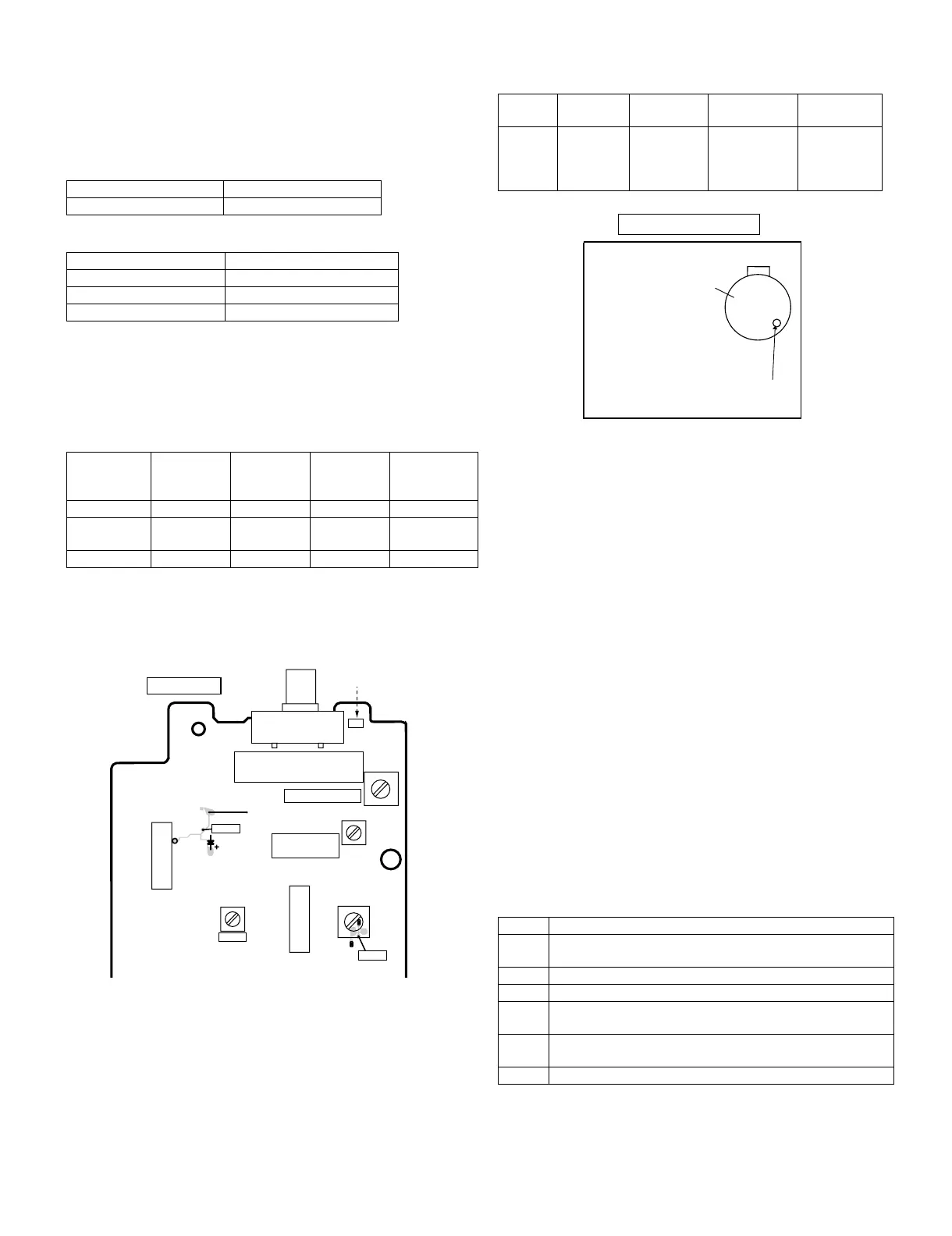
Figure 1
Error Explanation
01 When Pickup set inner position, inner switch cannot detect
'ON' level for 10 secs.
10* CAM error. Can't detect CAM switch when CAM is moving.
11* When it detect cam operation error during initialize process.
20* TRAY error. Can't detect TRAY switch when TRAY is mov-
ing.
21* When it detect TRAY operation error during initialize pro-
cess.
31 When it change to CD function, DSP cannot read initial data.
TAPE MECHANISM
Tape
Motor
Variable Resistor in motor
 Loading...