Basic
SAFETY PRECAUTION
IMPORTANT SERVICE SAFETY NOTES.............i
Precautions for using lead-free solder ..............vi
CHAPTER 1. OPERATION MANUAL
[1] Specifications ................................................. 1-1
[2] Parts Name and Basic Operation................... 1-2
[3] DIMENSIONS ................................................ 1-8
[4] Regarding the lamp........................................ 1-9
CHAPTER 2. REMOVING OF MAJOR PARTS
[1] Removing the lamp door and the lamp unit........ 2-1
[2] Removing the top body .................................. 2-1
[3] Removing the main PWB unit ........................ 2-2
[4] Removing the speaker, fan, and power
supply ballast unit........................................... 2-2
[5] Removing the optical mechanism unit and
RC light receiver PWB ................................... 2-3
[6] Removing the photosensor PWB unit,
blower fan, DMD PWB, and DMD .................. 2-3
CHAPTER 3. THE OPTICAL UNIT OUTLINE
[1] THE OPTICAL UNIT OUTLINE...................... 3-1
CHAPTER 4. ELECTRICAL ADJUSTMENT
[1] ELECTRICAL ADJUSTMENT........................ 4-1
[2] Adjustment mode process menu.................... 4-4
CHAPTER 5. TROUBLE SHOOTING TABLE
[1] TROUBLE SHOOTING TABLE .....................5-1
CHAPTER 6. BLOCK DIAGRAM/OVERALL WIRING
DIAGRAM
[1] BLOCK DIAGRAM.........................................6-1
[2] OVERALL WIRING DIAGRAM......................6-3
CHAPTER 7. PRINTED WIRING BOARD
[1] MAIN Unit ......................................................7-1
[2] DMD Unit .......................................................7-9
[3] BALLAST POWER Unit............................... 7-11
[4] BALLAST CONTROL Unit...........................7-17
[5] PHOTOSENSOR Unit .................................7-19
[6] R/C Unit .......................................................7-20
CHAPTER 8. WAVEFORMS
[1] WAVEFORMS ...............................................8-1
CHAPTER 9. SCHEMATIC DIAGRAM
[1] DESCRIPTION OF SCHEMATIC DIA-
GRAM............................................................9-1
[2] SCHEMATIC DIAGRAM ................................9-2
Parts Guide
SERVICE MANUAL
CONTENTS
Parts marked with " " are important for maintaining the safety of the set. Be sure to replace these parts with specified ones for maintaining the
safety and performance of the set.
This document has been published to be used for
after sales service only.
The contents are subject to change without notice.
TopPage
XR-10X-L/XR-10S-L/XG-MB50X-L/XR-11XC-L/XR-HB007X-L
No. S06X4XR10XLSL
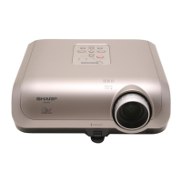
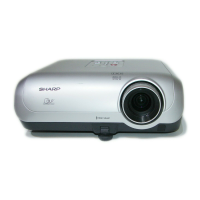
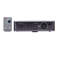
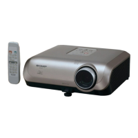
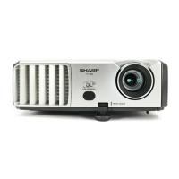
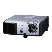
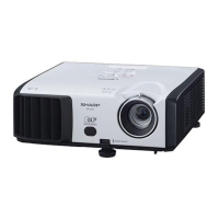
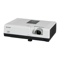
MULTIMEDIA PROJECTOR
XG-MB50X-L
XR-10S-L
XR-10X-L
XR-HB007X-L
XR-11XC-L
MODELS