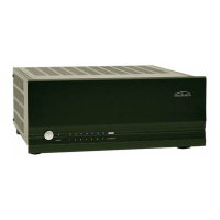
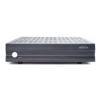
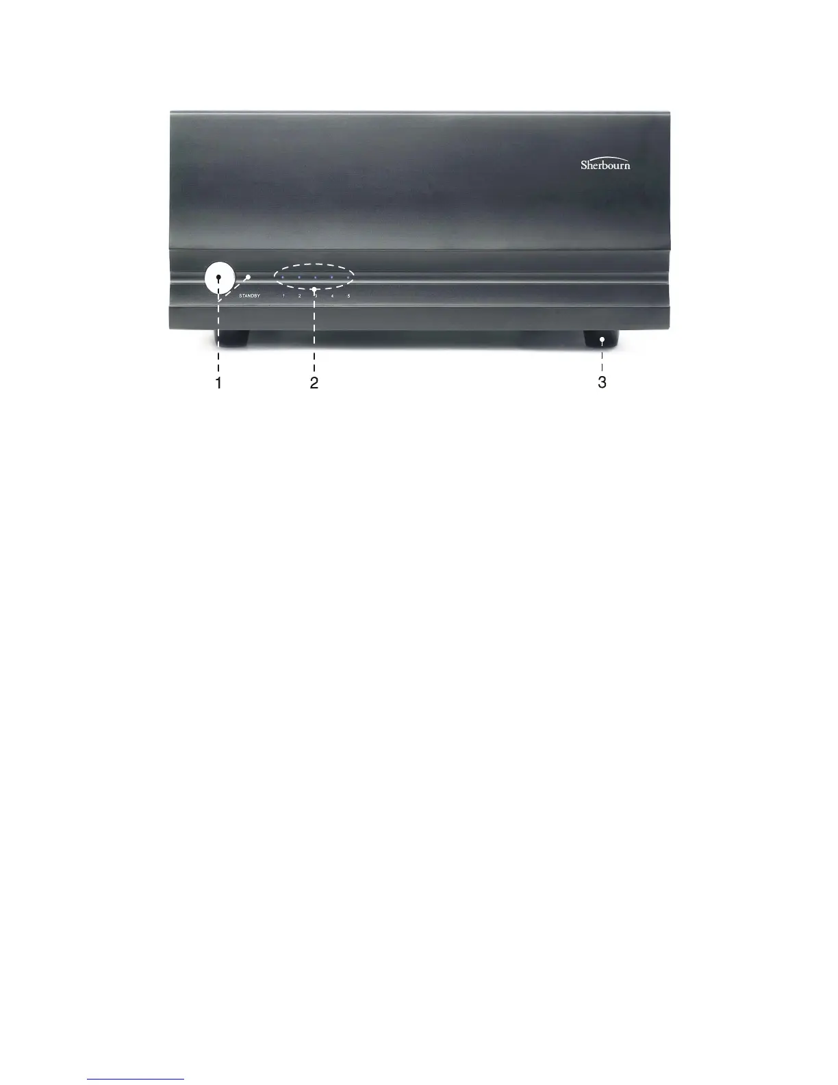
Front Panel Layout
1. Front Panel Power Switch
This switch provides the ON/OFF control of the 5-200 from the front
panel. When the unit is off and in standby mode, the switch illuminates
amber. Automatic switching is accomplished with the 3.5mm trigger in-
put on the rear panel using a 5-12VDC control signal.
2. Front Panel LED Display
The front panel display contains Status LED lighting to indicate the con-
dition of the 5-200.
• NO LED = Amplifier is OFF
• BLUE LED = Normal operational
• FLASHING RED LED = Fault Condition - see “Troubleshooting”
section for details.
Note: The amplifier rear panel has an LED Status Selector which can
turn the blue LEDs off.
3. Rubber Feet
Do not remove the feet from your amplifier. In addition to minimizing
vibration and insulating the amplifier from the surface it is placed on,
these feet are essential in allowing airflow under the amplifier for proper
cooling.
7
 Loading...