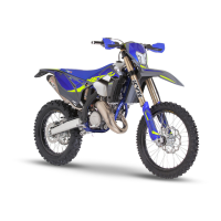
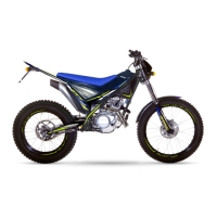
Do you have a question about the SHERCO 125 SE FACTORY and is the answer not in the manual?
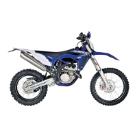
Detailed specifications for the engine, including type, displacement, bore, and other key parameters.
Specifications for the carburetor, including type, needle position, and jet sizes for optimal performance.
Settings and specifications for the KAYABA USD Ø48mm front fork for adjustment.
Step-by-step guide for safely removing the engine from the motorcycle chassis.
Procedure and torque values for reinstalling the engine back into the chassis.
Procedure for draining the gearbox oil before disassembly.
Steps to remove the cylinder head, cylinder, and piston from the engine.
Procedure for disassembling the clutch cover and its components.
Steps to remove the clutch pressure plate and discs from the clutch assembly.
Procedure for removing the electric starter motor from the engine.
Steps to remove the main transmission components, including gears and shafts.
Procedure for removing the gearbox locking mechanism for the selection system.
Steps to remove the ignition system components, like the rotor and nut.
Procedure for removing the starter motor unit from the engine casing.
Steps to remove the air intake pipe and clapper box assembly.
Procedure for separating the engine crankcase halves carefully.
Steps to remove the speed selection mechanism, including forks and drum.
Procedure for checking and servicing the connecting rod assembly and bearings.
How to measure the exterior diameter of the engine's balance masses.
Procedure to measure the radial clearance of the crankshaft crank head.
Procedure to measure the lateral clearance of the crankshaft crank head.
How to check for crankshaft radial runout (eccentricity) using a dial gauge.
Inspection points for the piston, including skirt wear and segment grooves.
How to measure the cross-sectional clearance of the piston rings within their grooves.
Method to measure cylinder bore diameter and check for wear or ovalness.
Steps to disassemble the exhaust valve system for inspection and cleaning.
Steps to correctly reassemble the exhaust valve system after servicing.
Procedure for setting the exhaust valve timing and clearances using special tools.
Inspection of the clapper box pipe and intake sleeve for wear or damage.
Inspection of clutch components like discs, springs, and push rod for wear.
Procedure for inserting the connecting rod assembly into the main crankshaft bearing.
Steps for assembling the gearbox shafts, forks, and pinions with lubrication.
Procedure for installing and securing the engine crankcase halves with gaskets.
Steps for assembling and installing the speed selection mechanism, including the star and forks.
Steps for assembling the main transmission, clutch drum, and securing with nuts.
Procedure for installing the clutch pressure plate, springs, and tightening screws.
Steps for installing the clutch casing, ensuring proper alignment of shafts and water pump.
Procedure for installing the piston and cylinder onto the crankshaft with correct orientation.
Steps for installing the cylinder head, using centering slugs and tightening bolts.
Procedure for installing the gearbox joint, clapper box, and intake pipe.
Steps to install the gearbox output pinion, washer, and tighten the nut.
Procedure for installing the ignition starter and lubricating its pinions.
Steps to assemble the ignition rotor, nut, bushings, and ignition cover.
Procedure for installing the electric starter motor into the engine casing.
Identification and location of key electrical components on the motorcycle.
How to test the cooling fan operation using a 12V battery connection.
Diagram showing the CDI unit connections and pin assignments.
Procedure to check the voltage regulator output and diode bridge functionality.
Method to check the motorcycle battery voltage and determine its state of charge.
Procedure to test the electric starter motor's operation and troubleshoot issues.
How to check alternator winding resistance and output voltage for the charging system.
How to connect the diagnostic tool with the keyless system for analysis.
Configuration options and adjustments for the diagnostic software.
Procedures for updating and synchronizing the diagnostic software with the system.
General guidelines and instructions on how to effectively use the diagnostic software features.
Diagram and details for the main electrical harness, including wire routing.
Wiring diagram for the standard homologated lighting system on the motorcycle.
Wiring diagram specific to the racing configuration of the lighting system.
Wiring diagram illustrating the connections for the cooling fan harness.
| Displacement | 124.8 cc |
|---|---|
| Cooling System | Liquid-cooled |
| Fuel System | Carburetor |
| Transmission | 6-speed |
| Bore x Stroke | 54mm x 54.5mm |
| Seat Height | 950 mm |
| Front Brake | 260mm disc |
| Rear Brake | 220mm disc |
| Clutch | Wet multi-disc |
| Frame | Chrome-molybdenum steel |
| Engine Type | 2-stroke, single-cylinder |