Do you have a question about the SHERCO 125 SE-R 2017 and is the answer not in the manual?
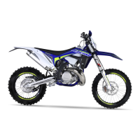
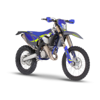
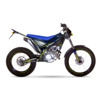
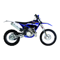
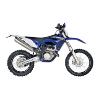
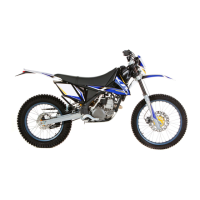
Details technical specifications for the engine, including type, displacement, bore/stroke, fuel, and coolant.
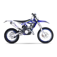
Details technical specifications for the motorcycle's chassis, suspension, brakes, and tires.
Provides original settings for the WP yoke suspension, including compression, recreation, and spring stiffness.
Details original settings for the WP suspension shock absorber, covering compression and spring stiffness.
Step-by-step instructions for safely removing the engine from the motorcycle frame, including necessary precautions.
Details the process for reassembling the engine into the frame, including valve cable tension adjustment.
Focuses on reassembly steps for the engine's valve system, including mapping contactor and cable tension.
Instructions for draining the gearbox oil by removing the drainage plugs.
Steps for removing the gearbox output pinion and the speed selector mechanism.
Detailed procedure for removing the cylinder head, cylinder, and piston assembly from the engine.
Instructions for removing the clutch casing and its associated joint.
Steps for removing the clutch pressure plate, springs, and discs from the engine.
Procedure for removing the electric starter motor from the engine assembly.
Detailed steps for removing the main transmission components, including the pinion and nut.
Specific instructions for removing the main transmission pinion, noting its pairing with the clutch housing.
Steps for removing the engine's locking mechanism, including the selection star.
Procedure for removing the ignition casing and its gasket.
Steps for removing the ignition system components, including the magnetic wheel.
Instructions for removing the starter motor from the engine.
Procedure for removing the intake pipe and clapper box assembly.
Steps for separating the engine's left and right half-casings, with precautions for the parting surface.
Procedure for removing the speed selection components, including fork shafts and drum.
Instructions for removing the primary and secondary shafts from their bearings.
Procedure for removing the connecting rod assembly from its bearing, with cleaning and inspection advice.
Procedure for checking and replacing the connecting rod assembly, including bearing and ring installation.
Instructions for measuring the exterior distance of the balance masses using a caliper.
Procedure for measuring crank head radial clearance using a dial gauge and checking against tolerances.
Method for measuring crank head lateral clearance and checking against tolerance limits.
Procedure for measuring crankshaft radial runout (eccentricity) using an alignment device and gauge.
Points to verify when reusing a piston, including apron smears and segment grooves.
Method for measuring the cross-sectional clearance of piston segments using a shim.
Procedure for detecting cylinder wear by measuring bore diameter and piston diameter.
Guidance on squish control, cylinder relining, and piston/cylinder dimension verification.
Steps for disassembling the exhaust valve system, including removing covers, cables, and pulley.
Procedure for controlling valve operations, ensuring central valve and boosters are fully open, and checking clearance.
Essential steps for adjusting the exhaust valve pulley clearance to guarantee optimal motorcycle operations.
Checks for the clapper box and intake sleeve, noting wear on carbon tabs and potential splitting.
Verification of clutch components including rod, springs, lined discs, and smooth discs for wear and thickness.
Instructions for inserting the connecting rod assembly into the ball bearing, ensuring proper crank positioning.
Steps for reassembling the transmission gearbox, including fork guiding, shafts, and drum insertion.
Procedure for assembling the engine half-casings, including lubrication, centring rings, and checking shaft rotation.
Detailed steps for reassembling the selection mechanism, including springs, spacers, and locking levers.
Instructions for reassembling the main transmission and clutch components, including pinion, washers, and nuts.
Steps for oiling and installing clutch discs, pressure plate, springs, and tightening screws.
Procedure for installing the clutch casing, ensuring proper alignment and mesh with the crankshaft.
Instructions for reassembling the piston and cylinder, including oiling, positioning, and securing.
Steps for cleaning, positioning, and tightening the cylinder head with new shoulder screws and washers.
Procedure for installing the clapper box, intake pipe, and associated screws and collar.
Steps for installing the gearbox output pinion, securing it with a nut and safety washer.
Instructions for installing the ignition starter and lubricating its pinions.
Procedure for assembling the ignition rotor, nut, and cover, including setting centring bushings.
Steps for assembling the electric starter, O-ring, and securing it with screws, plus clutch control rod insertion.
Lists tightening torques for various engine components, including screws, nuts, and sensor.
Provides carburettor settings (air screw, injectors, needle) based on altitude and temperature.
Measures stator winding resistance and checks for continuity between windings and chassis ground.
Tests voltage regulator for alternating and continuous current outputs at different engine speeds.
Detailed wiring diagram for the main electrical bundle, showing connections and component layouts.
Wiring diagram specifically for the front light beam assembly of the 125 SE-R model.
Wiring diagram for the racing version's front light beam assembly.
Wiring diagram for the accessory bundle, showing connections for additional equipment.
| Displacement | 124.8 cc |
|---|---|
| Bore x Stroke | 54 mm x 54.5 mm |
| Transmission | 6-speed |
| Fuel System | Carburetor |
| Front Suspension Brand | WP |
| Front Suspension Diameter | 48 mm |
| Rear Suspension Brand | WP |
| Front Brake | Disc |
| Front Brake Diameter | 260 mm |
| Rear Brake | Disc |
| Rear Brake Diameter | 220 mm |
| Seat Height | 950 mm |
| Engine Type | 2-stroke |
| Cooling System | Liquid-cooled |
| Rear Suspension | Shock absorber |
| Rear Suspension Type | Monoshock |
| Dry Weight | 94 kg |