Do you have a question about the Shimadzu UV-1700 series and is the answer not in the manual?
Explains procedures for installing, performance checking, troubleshooting, and adjusting the UV-1700.
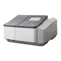
Describes the UV-1700 PharmaSpec spectrophotometer and its features.
States prerequisites for using the manual and Shimadzu's responsibility.
Details the locations and nature of warning labels on the instrument.
Lists standard contents of the UV-1700 and how to check them.
Specifies environmental and physical parameters for installing the instrument.
Provides procedures for power check, grounding, and cable connection.
Details the steps for performing instrument baseline correction after installation.
Provides important notes for various performance checks.
Explains how to use the instrument's validation functions.
Describes the procedure to check ROM checksum values.
Details methods for checking wavelength accuracy using D2 lamp or Holmium filter.
Explains how to check wavelength repeatability.
Describes how to measure and check the resolution.
Explains how to measure time variation for baseline stability.
Details how to correct and check baseline flatness.
Explains how to measure and check P-P and RMS noise levels.
Describes how to check photometric accuracy using NIST substandard filters.
Explains how to check photometric repeatability.
Details how to measure stray light using aqueous solutions or a UV-39 filter.
Outlines checks to ensure specifications are met after installation.
Covers checks for cooling fan operation and sample compartment cleanliness.
Includes checks for performance and light source.
Lists probable causes and actions for initialization errors.
Provides causes and actions for baseline flatness issues.
Lists causes and actions for exceeding noise level specifications.
Details causes and actions for wavelength accuracy issues.
Outlines causes and actions for repeatability problems.
Describes how to remove the main unit cover.
Details the procedure for removing the console PCB.
Explains how to remove the preamplifier PCB.
Describes the procedure for removing the power PCB.
Details the procedure for removing the CPU PCB.
Explains how to replace the ROM.
Provides steps for replacing the backup battery.
Lists necessary jigs and tools for adjustments.
Covers launching maintenance mode and drive system checks.
Details the procedure for adjusting the optical axis.
Explains how to adjust the light source optical axis.
Describes how to adjust the grating ruling and inclination.
Details the procedure for double beam optics adjustment.
Explains how to write constants into EEPROM.
Describes the procedure for exit slit focusing adjustment.
Details the steps for wavelength correction.
Shows the optical system diagram and explains its components.
Describes the beam position and size in the sample compartment.
Presents the electric system diagram of the UV-1700.
Explains the function of each unit and the block diagram.
Lists instrument configurations and associated part numbers.
Details parts for the UV-1700 main unit.
Lists components within the main unit assembly.
Details parts belonging to the cover unit.
Lists components of the transformer assembly.
Details parts included in the light source assembly.
Lists components of the optical unit assembly.
Details parts for the cell housing assembly.
Lists components of the slit and filter assembly.
Details parts for the CPU PCB assembly.
Lists components of the power PCB assembly.
Details parts for the preamplifier PCB assembly.
Lists components of the console PCB assembly.
Shows the electrical block diagram of the UV-1700.
Refers to the CPU Printed Circuit Board diagram.
Refers to the Preamplifier Printed Circuit Board diagram.
Refers to the Power Printed Circuit Board diagram.
Refers to the Console Printed Circuit Board diagram.
| Brand | Shimadzu |
|---|---|
| Model | UV-1700 series |
| Category | Measuring Instruments |
| Language | English |