2. SPECIFICATIONS VM-5S
-2-
Monitor range Input signal Recorder output Relay output
1 to 1,000rpm 1 VK,RD,FK Series*1 0 4 to 20mADC
2 to 2,000rpm 2 VE Series*2 1 1 to 5VDC
1
CH1 : 4 points (SR1,SR2,SR3,SR4)
SR1,SR2,SR3,SR4 Individual output
6
CH1 : 2 points (SR1,SR2) CH2 : 2 points (SR3,SR4)
SR1,SR3 OR output SR2,SR4 OR output
3 to 5,000rpm 3 MS Series*3
4 to 10,000rpm 4 VC Series*2
2
CH1 : 2 points (SR1,SR2) CH2 : 2 points (SR3,SR4)
SR1,SR3 Individual output SR2,SR4 Individual output
7
CH1 : 2 points (SR1,SR2) CH2 : 2 points (SR3,SR4)
SR1,SR3 OR output SR2,SR4 AND output
5 to 15,000rpm
2
Output card
/IS or /RE
option
6 to 20,000rpm
3
CH1 : 2 points (SR1,SR2) CH2 : 2 points (SR3,SR4)
SR1,SR3 Individual output SR2,SR4 OR output
8
CH1 : 2 points (SR1,SR2) CH2 : 2 points (SR3,SR4)
SR1,SR3 AND output SR2,SR4 Individual output
7 to 30,000rpm
8 to 50,000rpm
4
CH1 : 2 points (SR1,SR2) CH2 : 2 points (SR3,SR4)
SR1,SR3 Individual output SR2,SR4 AND output
A
CH1 : 2 points (SR1,SR2) CH2 : 2 points (SR3,SR4)
SR1,SR3 AND output SR2,SR4 OR output
A to 99,999rpm
5
CH1 : 2 points (SR1,SR2) CH2 : 2 points (SR3,SR4)
SR1,SR3 OR output SR2,SR4 Individual output
B
CH1 : 2 points (SR1,SR2) CH2 : 2 points (SR3,SR4)
SR1,SR3 AND output SR2,SR4 AND output
Speed relay
type
(SR1)
Speed relay
type
(SR2)
Speed relay
type
(SR3)
Speed relay
type
(SR4)
Hysterisis set value
(shaped waveform circuit)
(CH1)
Hysterisis set value
(shaped waveform circuit)
(CH2)
Alarm reset
(SR1)
Alarm reset
(SR2)
Alarm reset
(SR3)
Alarm reset
(SR4)
Alarm reset
(OK)
0 1.0V 0 1.0V 0 AUTO-RESET 0 AUTO-RESET 0 AUTO-RESET 0 AUTO-RESET 0 AUTO-RESET
0
Over
speed
0
Over
speed
0
Over
speed
0
Over
speed
1 0.1V 1 0.1V 1 SELF-HOLD 1 SELF-HOLD 1 SELF-HOLD 1 SELF-HOLD 1 SELF-HOLD
2 0.2V 2 0.2V 1 Under
speed
1
Under
speed
1
Under
speed
1
Under
speed
3 0.5V 3 0.5V
Relay mode
(SR1)
Relay mode
(SR2)
Relay mode
(SR3)
Relay mode
(SR4)
Relay mode
(OK)
First
output*4
Trigger
mode*5
Monitor/pulse
output
Isolate output
Recorder option
output
Input power supply
requirements
Tropical
spec.
CE
marking
0 OFF 0 AUTO 0 4 to 20mADC 2 0 to -10VDC 0 85 to 264VAC
0
NORMALLY
DE-ENERGIZED
0
NORMALLY
DE-ENERGIZED
0
NORMALLY
DE-ENERGIZED
0
NORMALLY
DE-ENERGIZED
0
NORMALLY
DE-ENERGIZED
1ON1MANUAL
0
Pulse
output
1 1 to 5VDC 3 0 to 10VDC 1 24VDC
2 0 to -10VDC 4 0 to -5VDC 2 110VDC
1
NORMALLY
ENERGIZED
1
NORMALLY
ENERGIZED
1
NORMALLY
ENERGIZED
1
NORMALLY
ENERGIZED
1
NORMALLY
ENERGIZED
1
Monitor
output
3 0 to 10VDC 5 0 to 5VDC
40 to -5VDC
50 to 5VDC
SPEED RELAY SET POINT
4 points (SR1,SR2,SR3,SR4)
SPEED RELAY SET
RANGE
More than 1rpm : Speed relay can be set in 1 rpm increments until
110% of monitor range
Less than 1rpm : Speed relay can be set in 0.1 rpm increment
INPUT
SPEED/INDICATED
SPEED CHANGED
RATIO
(NON-STANDARD
SPECIFICATION)
If the indicated rotation speed is different from the input rotation
speed, enter into the space below.
Input ratio speed
rpm rpm
In case of a magnification more than 1, the resolution
deteriorates in proportion to the magnification factor.
SPEED RELAY SET ACCURACY
±1 digit or less(on digital indicator)
SPEED RELAY OUTPUT 4 points (SR1,SR2,SR3,SR4)
ALARM OUTPUT 1 points (OK) or 2 points (OK1,OK2)
ROTOR SPEED LCD digital meter with 5 digits (7 segments, with back light)
LCD bar graph meter (40 segments, with back light)
SPEED RELAY
INDICATOR
SR1,SR3 : (yellow LED)
SR2,SR4 : (red LED)
SPEED RELAY SET
VAL UE
SR1 :
SR2 :
SR3 :
SR4 :
SR2 ≥ SR1 SR4 ≥ SR3
(SR2 ≤ SR1 SR4 ≤ SR3 in case of both under speed)
Preset to 50% of monitor range unless specified otherwise.
ABNOR. ALARM INDICATOR
OK : (green LED)
BYPASS INDICATOR BYPASS :(red LED)
TRANSDUCER INPUT VK, RD,FK Series, VE Series, MS Series, VC Series
Number of input points : 2 points
INPUT IMPEDANCE Approx.5kΩ
INPUT VOLTAGE
Min.:2Vpk-pk, Max.:100Vpk-pk
MIN. PULSE WIDTH
Approx.50µsec
MIN. INDICATED FREQUENCY
Lower of 1Hz or under speed setting.
MAX. INPUT FREQUENCY
10kHz
NO. OF INPUT PULSE 1 to 120 pulse
SPEED RELAY
HYSTERESIS
Speed relay hysteresis can be specified from 0 to 100rpm. (1rpm step)
SR1 :
SR2 :
SR3 :
SR4 :
Preset to 10rpm unless specified otherwise.
NO. OF INPUT P/R Can be specified from 1 to 120 pulse.
Pulses/rev. :
TRIGGER MODE AUTO, MANUAL (selectable)
In case of auto trigger mode, input pulse duty ratio should be
between 10 and 90% and input pulse frequency should be 1Hz and
over. it depends on the target.
EXTERNAL CONTACT INPUT
(FROM REAR PANEL)
Contact type : Dry contact
Contact for external reset
DIGITAL METER
±(0.003% of rdg. +1 digit) at 25°C(77°F)
±(0.03% of rdg.+1 digit) at 0 to 65°C(32 to 149°F)
BAR GRAPH METER ±2.5% of F.S.
RECORDER OUTPUT
CONVERSION ACCURACY
±0.5% of F.S. at 25°C(77°F)
±2.0% of F.S. at 0 to 65°C (32 to 149°F)
RECORDER OUTPUT
(FROM REAR PANEL)
Voltage or current output proportional to monitor range
1 to 5VDC (output impedance : 250Ω)
4 to 20mADC (max. load resistance : 500Ω)
0 to -10VDC*,0 to 10VDC*,0 to -5VDC*,0 to 5VDC*
(output impedance : 100() (*option)
Number of output points : 2 points
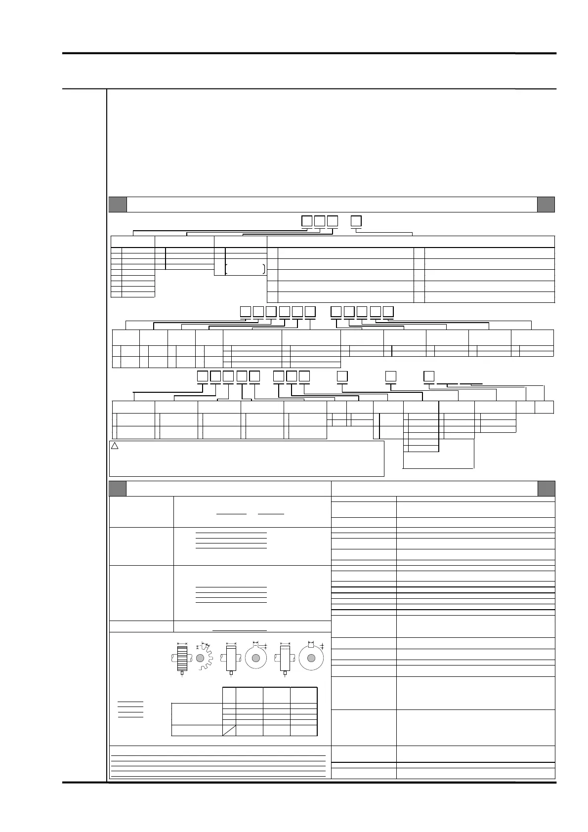
DIMENSION OF TARGET
(Model VK, RD,FK)
CAUTION) To detect a projection(gear), provide surface A of the projection with a concentric
curve.
Do not make it flat.
A=
mm
B=
mm
C=
mm
D=
mm
MONITOR/PULSE
OUTPUT
(FROM FRONT, REAR
PANEL )
Monitor output/Pulse output, selectable
Monitor output : Input signal is output via a buffer amplifier.
Signal level : -0.8 to -22VDC(VK, RD)
±15V(MS),0 to 15VDC(VE), 0 to 5VDC(VC)
Pulse output : Shaped pulse signal is output via a buffer amplifier.
Signal level : -1 to +1V(PL),4 to 6V(PH)
Output impedance : Approx.100( (load resistance 50k( or more)
TEMPERATURE RANGE
Operating temperature : 0 to 65°C(32 to 149°F)
Storage temperature : -30 to +85°C(-22 to +185°F)
Relative humidity : 20 to 95%RH(noncondensing)
MATERIAL AND FINISH
Face plate : Aluminum Munsell N-4.0 (equiv.)
OTHERS
MASS
Monitor : max.0.7kg
(including single unit instrument rack max.2.5kg)
VM-5S- -
Ordering Information Standard Specifications
- -
! WARNING
This monitor is designed for monitoring but not for controlling the rotor speed.
• Use the speed relay contact only for alarms.
• Use the recorder output only for data recording.
• When a zero speed system is designed using this monitor, other enable contact should be provided by the
customer for the reliable and safe engagement of the turning gear.
Note)
*1 VK transducer can not detect the wire break
in the sensor system, so RD or FK driver
which can detect the wire break shall be
recommended. Especially in case of the
application for zero speed monitor, RD or
FK driver shall be strongly recommended
for safety.
Model Code / Additional Spec. Code( )
No entry if additional
spec. code is not specified.
- -
/TRP/CEM /(IS
or RE
)/5G
When recorder output code 2
is selected, specify this
o
tion code.
Note) *2 Input abnormal alarm is not applicable in case of VC and VE input signal.
*3 Short circuit is not detectable in case of MS in
ut si
nal.
Note) *4 It is necessary to set all
monitor units in the same
rack in first out function
ON when it is used first ou
function.
*5 Auto trigger mode is not
selectable, in case of zero
speed use.
39511E4.5
Input
VK-202
RD-05A
FK-202F
VK-452A
FK-452F
VK-302P
A ≥ 6 ≥16 ≥ 8
B ≥ 7 ≥20 ≥ 8
C ≥ 2.5 ≥ 4.5 ≥ 2.5
Dimension of target
[recommended]
(mm)
D ≥ 16 ≥ 36 ≥ 20
Set gap
[recommended](mm)
1.0 to 1.5 2.5 to 3.5 1.0 to 1.5
D
B
C
D D
C
B
C
 Loading...