

B
Brittany TaylorAug 15, 2025
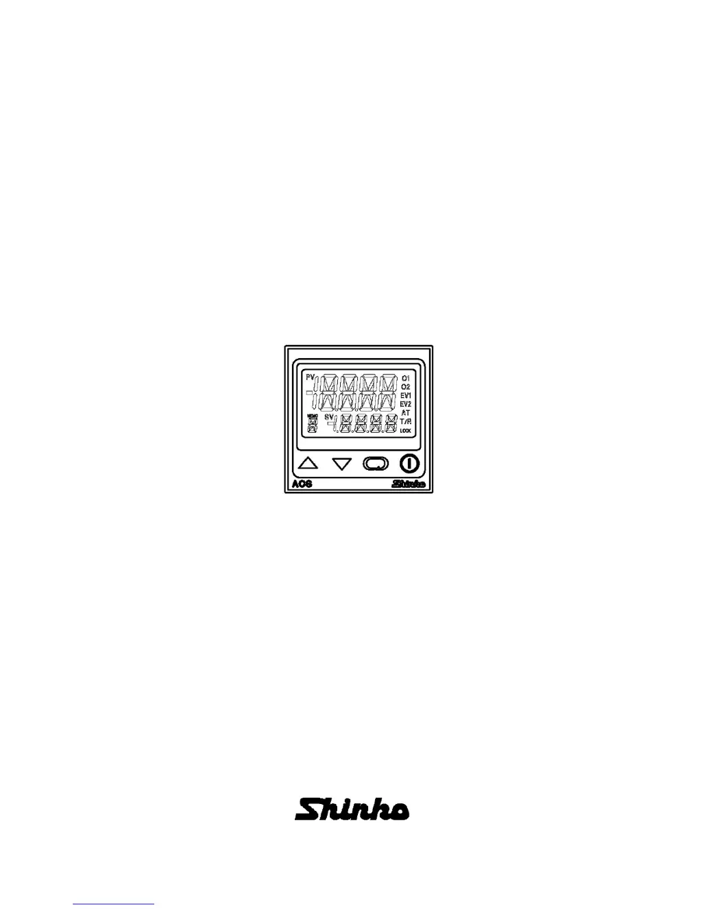
Why can't I set the SV, P, I, D, proportional cycle or alarm value on my Shinko ACS-13A?
- DDaniel SmithAug 15, 2025
If you are unable to set the SV, P, I, D, proportional cycle, or alarm value on your Shinko Controller, it might be due to the set value lock (Lock 1 or Lock 2) being active. To resolve this, release the lock in the [Set value lock] settings. Alternatively, AT or auto-reset may be in progress. If it is AT, cancel it. Auto-reset takes approximately 4 minutes to complete.


