


B
browntiffanyAug 14, 2025
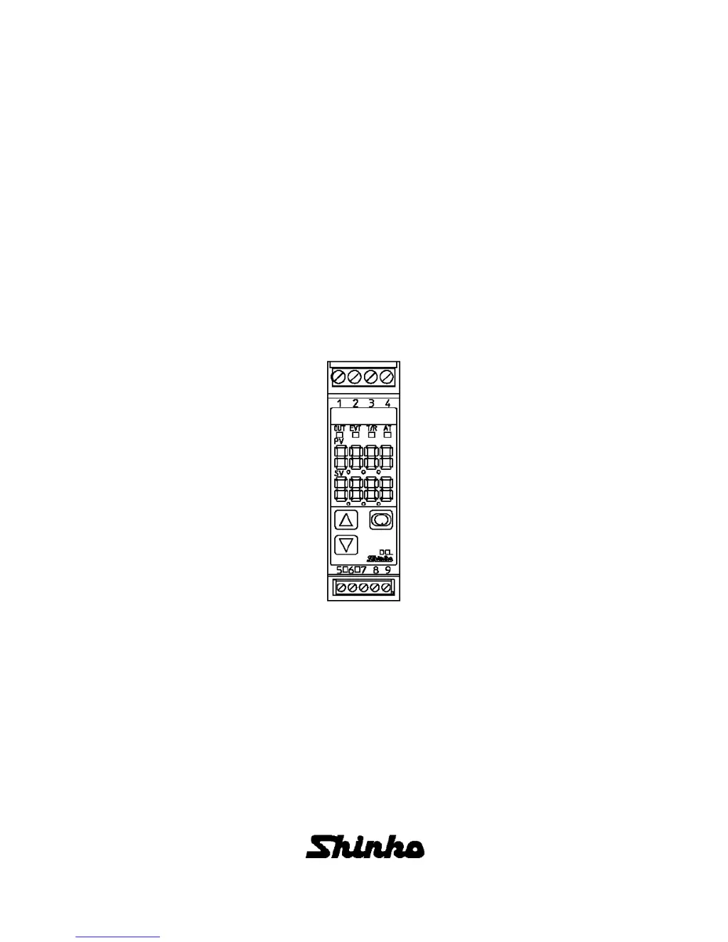
Why is the Shinko DCL-33A Controller PV display abnormal or unstable?
- MmartinandreAug 14, 2025
An abnormal or unstable PV display indication on your Shinko Controller could be due to several reasons: * The sensor (input) designation might be incorrect; ensure the correct sensor is set. * The polarity of the sensor input might be incorrect; check and correct the wiring. * The temperature unit ( / ) might be mistaken; set the correct unit. * AC might be leaking from the controlled object to the thermocouple or RTD; prevent AC leakage into the controlled object.


