27
6. Simplified Converter Function
Caution
• The converter function is selectable only for the Direct current output type.
• When using this controller as a converter, take 1 second into consideration since input/output
response time is approx. 1 second.
• When switching from converter to controller function, the control parameters and values set
by converter function are retained even if the function is switched to controller function.
So, after switching to the controller function, correct the converter parameters to the
controller parameters.
The converter function of this instrument converts each input (thermocouple, RTD, DC voltage and direct
current input) value to “4 to 20 mA DC”, using the control parameters of the controller, and outputs it.
When this instrument is used as a converter, follow steps (1) to (7) described below.
After steps (1) to (7) are finished, this instrument can be used as a converter.
(1) Wire this unit (Power supply, Input and Output).
(2) Turn the power supply of this unit ON.
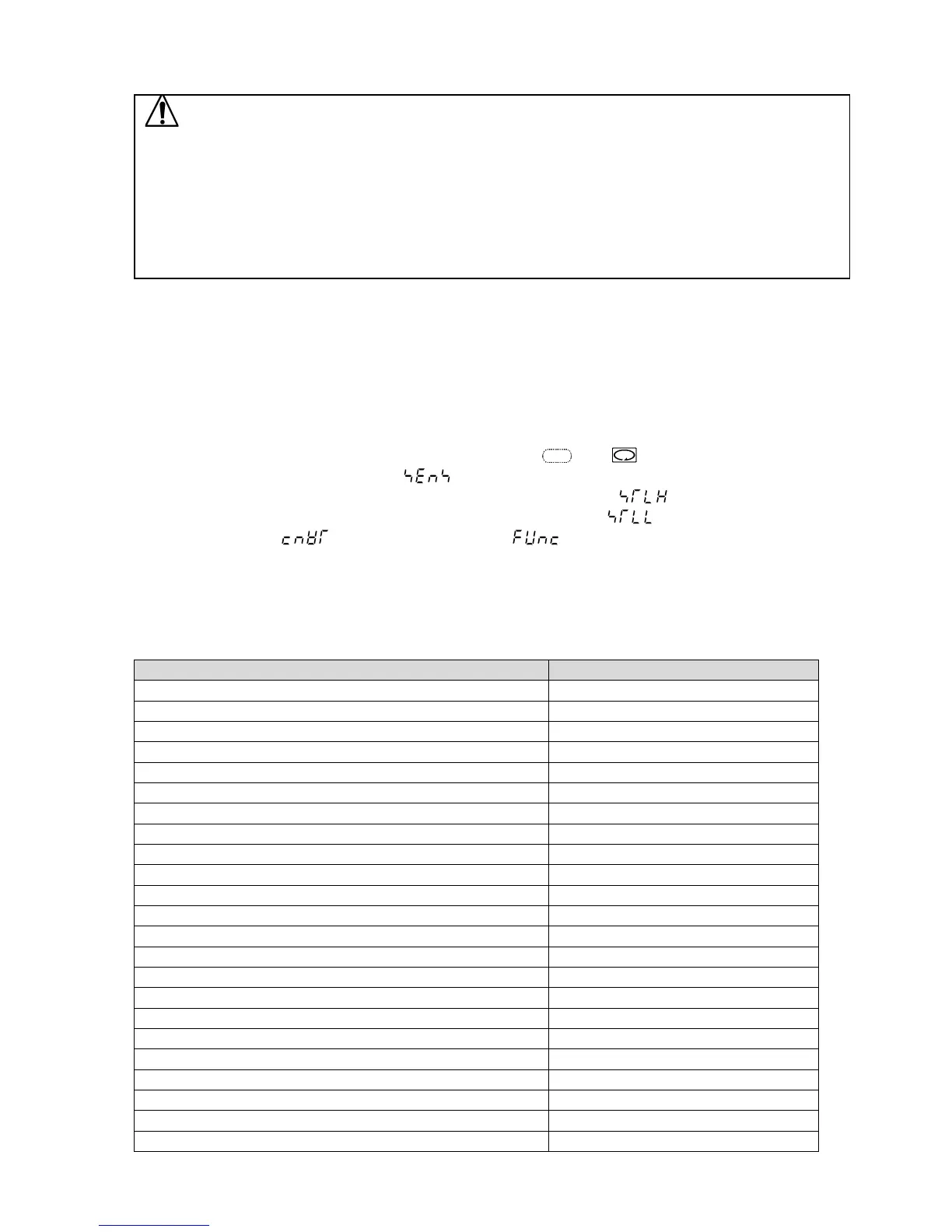
(3) Enter ‘Auxiliary function setting mode 2’ by pressing the and key (for approx. 3 sec).
(4) Select a sensor type in [Input type] ( ).
(5) Set the high limit of the value to be converted in [Scaling high limit] ( )”.
(6) Set the low limit of the value to be converted in [Scaling low limit] ( )”.
(7) Select Converter ( ) in [Controller/Converter] ( )”.
• To activate the alarm action by Converter function, set the alarm type to Process alarm.
If ‘Converter’ is selected in [Controller/Converter] in Auxiliary function setting mode 2,
parameters below are automatically set. (Table 6-1)
(Table 6-1)
Setting Item Setting Value
SV1 (*1) Scaling low limit
SV2 (*1) Scaling low limit
Integral time 0
Derivative time 0
OUT1 proportional band (*1) Scaling span
OUT2 proportional band (*1) Scaling span
Reset (*3) 0.0
Alarm 1 value 0 Enabled/Disabled Disabled
Alarm 1 value 0
Alarm 1 high limit alarm value 0
Alarm 2 value 0 Enabled/Disabled Disabled
Alarm 2 value 0
Alarm 2 high limit alarm value 0
Alarm 3 value 0 Enabled/Disabled Disabled
Alarm 3 value 0
Alarm 3 high limit alarm value 0
Alarm 4 value 0 Enabled/Disabled Disabled
Alarm 4 value 0
Alarm 4 high limit alarm value 0
Loop break alarm time 0
Loop break alarm span 0
Direct/Reverse action Direct action
Event input DI allocation 000


 To Next Page