38
10. Specifications
10.1 Standard Specifications
Model: DIN rail mounted indicating controller
Mounting: DIN rail
Setting: Input system using membrane sheet key
Display:
PV Display: Red LED 4 digits, character size 7.4 x 4.0 mm (H x W)
SV Display: Green LED 4 digits, character size 7.4 x 4.0 mm (H x W)
Input:
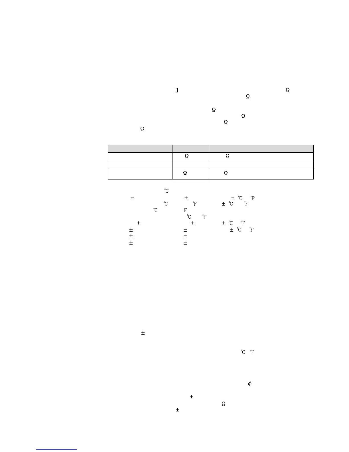
Thermocouple: K, J, R, S, B, E, T, N, PL- , C (W/Re5-26) External resistance: 100 max.
However, for thermocouple B, external resistance: 40 max.
RTD: Pt100, JPt100, 3-wire type
Allowable input lead wire resistance (10 max. per wire)
Direct current: 0 to 20 mA DC, 4 to 20 mA DC, input impedance 50
If direct current input (Externally mounted 50 shunt resistor) is designated,
connect 50 shunt resistor (sold separately) between input terminals.
Allowable input current: 50 mA max.
DC voltage:
0 to 1 V DC 0 to 5 V DC, 1 to 5 V DC, 0 to 10 V DC
Input impedance
1 M min. 100 k min.
Allowable input voltage 5 V max. 15 V max.
2 k max.
100 max.
Indication performance:
Basic accuracy (at ambient temperature 23 , for a single unit mounting):
Thermocouple: Within 0.2% of input span 1 digit, or within 2 (4 ) whichever is greater
R, S inputs, 0 to 200 (0 to 400 ): Within 6 (12 )
B input, 0 to 300 (0 to 600 ): Accuracy is not guaranteed.
K, J, E, T, N input, less than 0 (32 ):
Within 0.4% of input span 1 digit, or 4 (8 ), whichever is greater
RTD: Within 0.1% of input span 1 digit, or within 1 (2 ) whichever is greater
DC voltage: Within 0.2% of input span 1 digit
Direct current: Within 0.2% of input span 1 digit
Input sampling period: 125 ms
Control performance: Same as setting accuracy and basic accuracy
Control action:
• PID control [with auto-tuning (AT) function]
• PI control: When derivative time is set to 0
• PD control (with manual reset function): When integral time is set to 0
• P control (with manual reset function): When derivative and integral time are set to 0
• ON/OFF control: When OUT1 proportional band is set to 0.0
OUT1 proportional band: 0.0 to 110.0% (ON/OFF control when set to 0.0)
Integral time: 0 to 3600 seconds (Disabled when set to 0)
Derivative time: 0 to 1800 seconds (Disabled when set to 0)
OUT1 proportional cycle: 1 to 120 seconds
ARW: 0 to 100%
Manual reset: Proportional band converted value
OUT1 high, OUT1 low limit: 0 to 100% (Direct current output type: –5 to 105%)
(Not available for ON/OFF control)
OUT1 ON/OFF hysteresis: Thermocouple, RTD input: 0.1 to 100.0 ( )
DC voltage, current input: 1 to 1000 (The placement of the
decimal point follows the selection.)
Control output (OUT):
• Relay contact: 1a, Control capacity: 3 A 250 V AC (Resistive load)
1 A 250 V AC (Inductive load cos = 0.4)
Electrical life: 100,000 cycles
• Non-contact voltage (for SSR drive): 12 V DC 15% Max. 40 mA DC (Short circuit protected)
•
Direct current: 4 to 20 mA DC, Load resistance: Max. 550
Output accuracy: Within 0.3% of the output span
Resolution: 12000