6
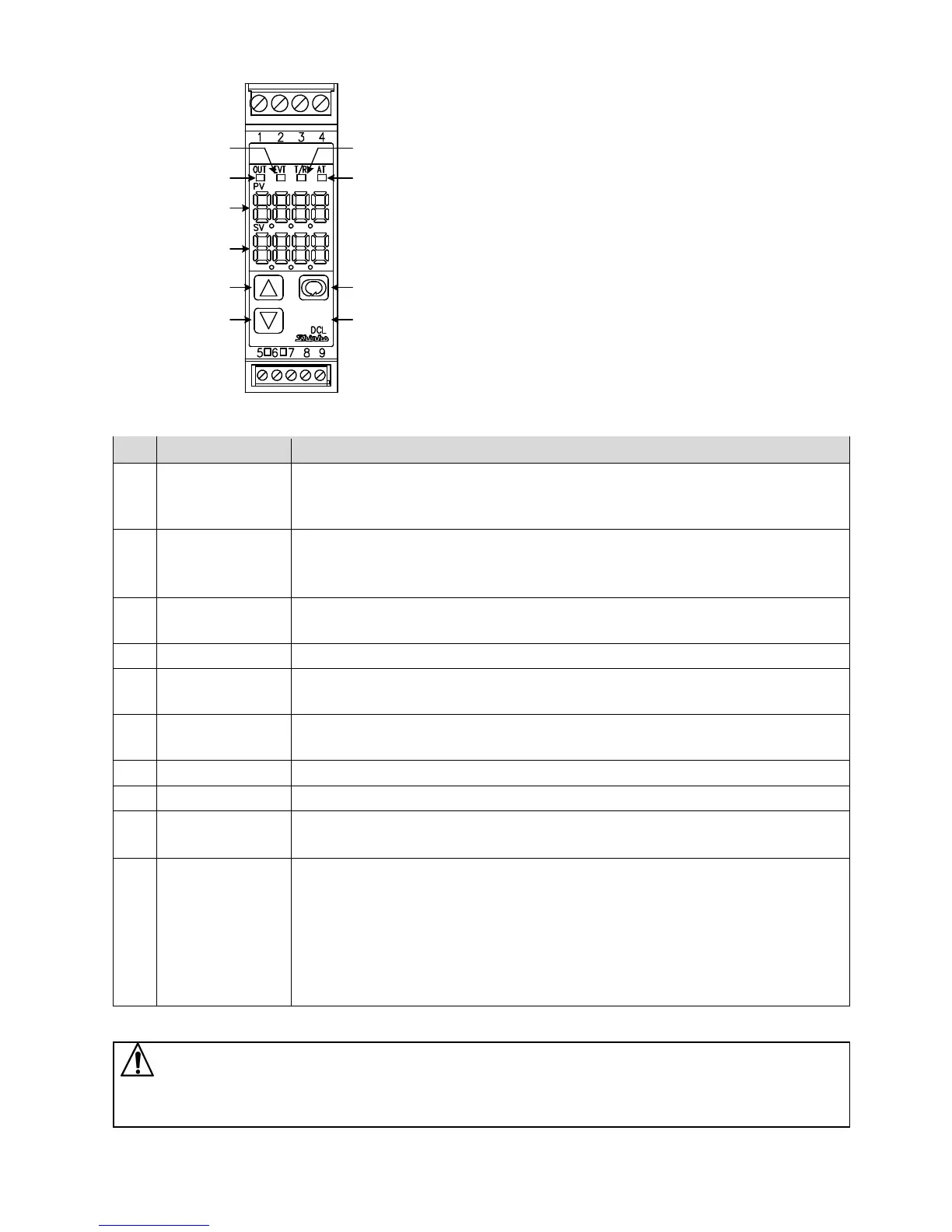
2. Name and Functions of Controller
(Fig. 2-1)
No. Name
Description
①
EVT indicator
The red LED lights when Event output [Alarm, Loop break alarm or Heater burnout
alarm (W option)] is ON.
The red LED also lights when control output OUT2 (DC option) is ON.
②
OUT indicator
The green LED lights when control output OUT1 is ON.
For direct current output, flashes in 125 ms cycles corresponding to the output
MV.
③
T/R indicator
The yellow LED flashes during serial communication (C5 option) TX output
(transmitting).
④
AT indicator
The yellow LED flashes while auto-tuning (AT) is performing.
⑤
PV Display
Indicates the PV (process variable), or setting characters in setting mode with a
red LED.
⑥
SV Display
Indicates the SV (desired value), output MV (manipulated variable) or the set value
in each setting mode with a green LED.
⑦
UP key
Increases the numeric value.
⑧
DOWN key
Decreases the numeric value.
⑨
MODE key
Switches the setting mode or registers the set data.
(Registers the set data by pressing the MODE key.)
⑩
SUB-MODE key
Enters Auxiliary function setting mode 2 in combination with the MODE key.
If ‘Control output OFF’ is selected in [SUB-MODE key function]: Turns all outputs
OFF as if the power were turned OFF.
If ‘Auto/Manual control’ is selected in [SUB-MODE key function]: Switches
Auto/Manual control.
If ‘Alarm HOLD cancel’ is selected in [SUB-MODE key function]: Cancels Alarm
HOLD.
Caution
When setting the specifications and functions of this controller, connect mains power cable to terminals 1 and 2
first, then set them referring to “5. Setup” before performing “3. Mounting to the control panel” and “4. Wiring”.
①
②
⑤
⑥
③
④
⑦
⑧
⑨
⑩