45
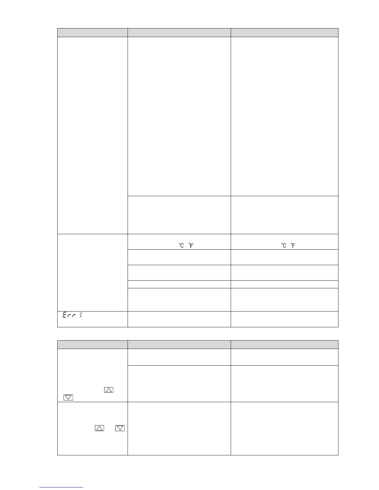
Problem Possible Cause Solution
The value set in
[Scaling low limit]
remains on the PV
Display.
Check whether the input signal wire
for DC voltage (0 to 5 V DC, 0 to 10
V DC) or direct current (0 to 20 mA
DC) is disconnected.
How to check whether the input
signal wire is disconnected
[DC voltage (0 to 5 V DC, 0 to 10 V
DC)]
If the input to the input terminal of
this controller is 1 V DC, and if a
value (converted value from Scaling
high, low limit setting) corre-
sponding to 1 V DC is indicated, the
controller is likely to be operating
normally, however, the signal wire
may be disconnected.
[Direct current (0 to 20 mA DC)]
If the input to the input terminal of
this controller is 4 mA DC, and if
a value (converted value from
Scaling high, low limit setting) corre-
sponding to 4 mA DC is indicated,
the controller is likely to be
operating normally, however, the
signal wire may be disconnected.
Check whether the input signal wire
for DC voltage (0 to 5 V DC, 0 to10
V DC) or direct current (0 to 20 mA
DC) is securely connected to the
controller input terminals.
Connect the signal wire to the
controller input terminals securely.
The indication of the
PV Display is abnormal
or unstable.
Check whether the sensor input or
temperature unit ( , ) is correct.
Set the sensor input and the
temperature unit ( , ) correctly.
Sensor correction value is not
suitable.
Set it to a suitable value.
Check whether the sensor
specification is correct.
Set the sensor specification properly.
AC leaks into the sensor circuit. Use an ungrounded type sensor.
There may be equipment that
interferes with or makes noise near
the instrument.
Keep the instrument clear of any
potentially disruptive equipment.
[ ] is indicated on
the PV Display.
The internal memory is defective. Please contact our main office or
dealers.
11.2 Key Operation
Problem Possible Cause Solution
• Settings (SV, P, I, D,
proportional cycle,
alarm value, etc.) are
impossible.
• The values do not
change by the or
key.
Set value lock (Lock 1 or Lock 2) is
selected.