
M
Michelle RiveraSep 23, 2025
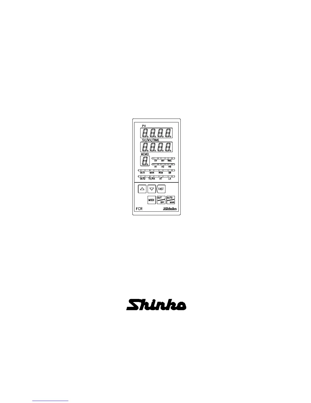
Why control is not performing on Shinko FCR-13A?
- VVanessa SmithSep 23, 2025
If control is not performing on your Shinko Controller and only the PV display is indicated, press the key to perform Program control. Alternatively, to perform Fixed value control, select the Fixed value control mode by pressing the key while holding down the key for approximately 3 seconds.


