T
Tammy ThompsonSep 2, 2025
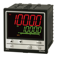
What to do if program control does not start on my Shinko Controller?
- MmcooperSep 2, 2025
If program control does not start even when the key is pressed in Program mode on your Shinko Controller, ensure that the step time has been set.