EasyManua.ls Logo

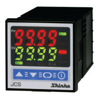
Shinko JCS-33A-R/M T6080 User Manual

Shinko JCS-33A-R/M T6080
20 pages
To Next Page IconTo Next Page
Page #1 background imageLoading...
Page #1 background image
1
INSTRUCTION MANUAL
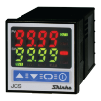
Micro-computer based digital indicating limit controller JCS-33A-R/M T6080
JCS33T6080E1 2006.12
To prevent accidents arising from the misuse of this controller, please ensure the operator receives this manual.
Safety precautions (Be sure to read these precautions before using our products.)
The safety precautions are classified into categories: “Warning” and “Caution”. Depending on circumstances,
procedures indicated by
Caution may be linked to serious results, so be sure to follow the directions for
usage.
Warning
Warning
To prevent an electric shock or fire, only our or other qualified service personnel may handle the inner
assembly.
• To prevent an electric shock, fire or damage to the instrument, parts replacement may only be undertaken
by our or other qualified service personnel.
Safety precautions
To ensure safe and correct use, thoroughly read and understand this manual before using this instrument.
• This instrument is intended to be used for industrial machinery, machine tools and measuring equipment. Verify
correct usage after consulting purpose of use with our agency or main office. (Never use this instrument for
medical purposes with which human lives are involved.)
• External protection devices such as protection equipment against excessive temperature rise, etc. must be
installed, as malfunction of this product could result in serious damage to the system or injury to personnel.
Also proper periodic maintenance is required.
• This instrument must be used under the conditions and environment described in this manual. We do not accept
liability for any injury, loss of life or damage occurring due to the instrument being used under conditions not
otherwise stated in this manual.
Caution with respect to Export Trade Control Ordinance
To avoid this instrument from being used as a component in, or as being utilized in the manufacture of weapons of
mass destruction (i.e. military applications, military equipment, etc.), please investigate the end users and the final
use of this instrument. In the case of resale, ensure that this instrument is not illegally exported.
Caution
• This instrument should be used according to the specifications described in the manual.
If it is not used according to the specifications, it may malfunction or cause fire.
Be sure to follow the warnings, cautions and notices. Not doing so could cause serious injury or malfunction.
Specifications of the JCS-33A and the contents of this instruction manual are subject to change without notice.
• This instrument is designed to be installed in a control panel. If it is not, measures must be taken to ensure
that the operator cannot touch power terminals or other high voltage sections.
• Be sure to turn the power supply to the instrument OFF before cleaning this instrument.
• Use a soft, dry cloth when cleaning the instrument.
(Alcohol based substances may tarnish or deface the unit.)
As the display section is vulnerable, do not strike or scratch it with a hard object.
Any unauthorized transfer or copying of this document, in part or in whole, is prohibited.
Shinko Technos CO., LTD. is not liable for any damages or secondary damages incurred as a result of using
this product, including any indirect damages.
Caution
Procedures which may lead to dangerous conditions and cause death or serious
injury, if not carried out properly.
Procedures which may lead to dangerous conditions and cause superficial to medium
injury or physical damage or may degrade or damage the product, if not carried out
properly.
Questions and Answers:

Shinko JCS-33A-R/M T6080 Specifications

General IconGeneral
BrandShinko
ModelJCS-33A-R/M T6080
CategoryController
LanguageEnglish

Summary

Safety Precautions

Warning and Caution Definitions

Explains the meaning of Warning and Caution labels for safe usage.

General Safety Guidelines

Provides essential rules for safe operation and handling of the instrument.

Export Trade Control

Guidance on preventing illegal export related to weapons of mass destruction.

Model Identification

Model Specifications

Details the JCS-33A-R/M T6080 model and its selectable options.

Model Label Interpretation

Explains how to read and understand the model designation on the unit.

Control Panel Overview

PV and SV Displays

Describes the function of the Process Variable (PV) and Set Value (SV) displays.

Indicator Lights

Explains the meaning of various indicator LEDs on the controller.

Operation Keys

Details the function of each key used for operation and setting.

Mounting to Control Panel

Site Selection and Environment

Specifies the recommended installation location and environmental conditions.

External Dimensions

Provides the physical size and mounting bracket details of the unit.

Panel Cutout Specifications

Details the required dimensions for cutting a panel hole for installation.

Mounting Procedures

Vertical Mounting

Instructions for mounting the controller vertically for IP66 compliance.

Bracket Attachment

Details on using mounting brackets and screws for secure installation.

Wiring Instructions

Pre-wiring Safety Warning

Emphasizes turning off power before wiring to prevent electric shock.

Terminal Block Configuration

Explains the wiring layout and terminal functions for power and signals.

Solderless Terminal Usage

Specifies the type and torque for solderless terminals.

Settings Configuration

Operation Procedure Overview

Outlines the sequence for setting input types, alarms, and desired values.

Main Setting Mode

Details setting the desired value (SV) and alarm action points.

Sub Setting Mode

Explains optional settings like value lock and sensor correction.

Setup Mode Parameters

Input Type and Scaling

Configuration of sensor input type, scaling limits, decimal point, and filter.

Alarm Settings

Configuration for A1 and A2 alarm types, hysteresis, and delayed timers.

Control Action Setup

Selection of High/Low limit control and output hysteresis.

Display and Setting Modes

Display Mode Selection

How to select items to be shown on the PV and SV displays.

Main Setting Mode Operations

Procedures for setting SV, A1, and A2 values.

Alarm Setting Ranges

Details the configurable ranges for different alarm types.

Sub Setting Mode Configuration

Set Value Lock

Functionality to lock settings to prevent errors.

Sensor Correction

How to adjust for sensor inaccuracies.

Communication Parameters

Settings for serial communication (protocol, speed, parity, stop bit).

Advanced Setup Mode

Input Type Configuration

Detailed selection of input types (thermocouple, RTD, DC) and units (°C/°F).

Scaling Limits and Filter

Setting scaling high/low limits and PV filter time constant.

Setup Mode Alarms and Control

Alarm Type and Action Selection

Configuration of A1/A2 alarm types and Energized/Deenergized actions.

Alarm Hysteresis and Timing

Setting hysteresis and delayed timers for alarms.

Control Action and Output Hysteresis

Setting High/Low limit control and output hysteresis.

Operation Modes and Running

Start Mode Selection

Configuration of Auto or Manual start for control action.

Sensor Correction Function

Explanation of how sensor correction works.

Running the Controller

Steps to power on, set values, and start control operation.

Control Action Explanation

High Limit Control Action

Explains the behavior of the high limit control sequence.

Low Limit Control Action

Explains the behavior of the low limit control sequence.

Start and Alarm Actions

Auto/Manual Start Behavior

Describes how auto and manual start modes affect control initiation.

A1/A2 Alarm Action Diagrams

Illustrates alarm actions (High/Low limit, standby) and output behavior.

Standard Specifications

General Specifications

Covers mounting, display, accuracy, and input/output details.

Control Action Specifications

Details limit control action and output hysteresis.

Circuit Insulation

Information on insulation resistance and dielectric strength.

Detailed Specifications

Environmental and Physical Specs

Ambient conditions, weight, dimensions, material, and color.

Input Abnormalities and Diagnostics

How the unit handles input issues, burnout, and self-diagnosis.

Optional Specifications

A2 Output and Serial Communication

Details on A2 output and C5 serial communication options.

External Reset and Terminal Cover

Information on SM external reset input and TC terminal cover.

Troubleshooting Guide

Display Indication Problems

Solutions for issues like "E", "HI"/"Lo", or flashing displays.

Operation and Control Issues

Key Operation Problems

Troubleshooting for issues with setting values or key input.

Control Performance Issues

Diagnosing and resolving problems like temperature not rising.

Related product manuals