17
Supply voltage : 100 to 240V AC 50/60Hz, 24V AC/DC 50/60Hz
Allowable voltage fluctuation: 100 to 240V AC: 85 to 264V AC,
24V AC/DC : 20 to 28V AC/DC
Power consumption : Approx. 8VA
Ambient temperature
: 0 to 50 (32 to 122 )
Ambient humidity : 35 to 85%RH (no condensation)
Weight : Approx. 200g
External dimensions : 48 x 48 x 95mm (W x H x D)
Material : Flame-resistant resin (Case)
Color : Light gray (Case)
Attached functions : [Set value lock], [Sensor correction], [Auto/Manual start],
[Input abnormality indication]
Thermocouple, RTD input:
If measured value exceeds Indication range high limit value, the PV display flashes “
”.
If measured value drops below Indication range low limit value, the PV display flashes “ ”.
If measured value goes out of the Control range, OUT (Limit control output) is turned OFF.
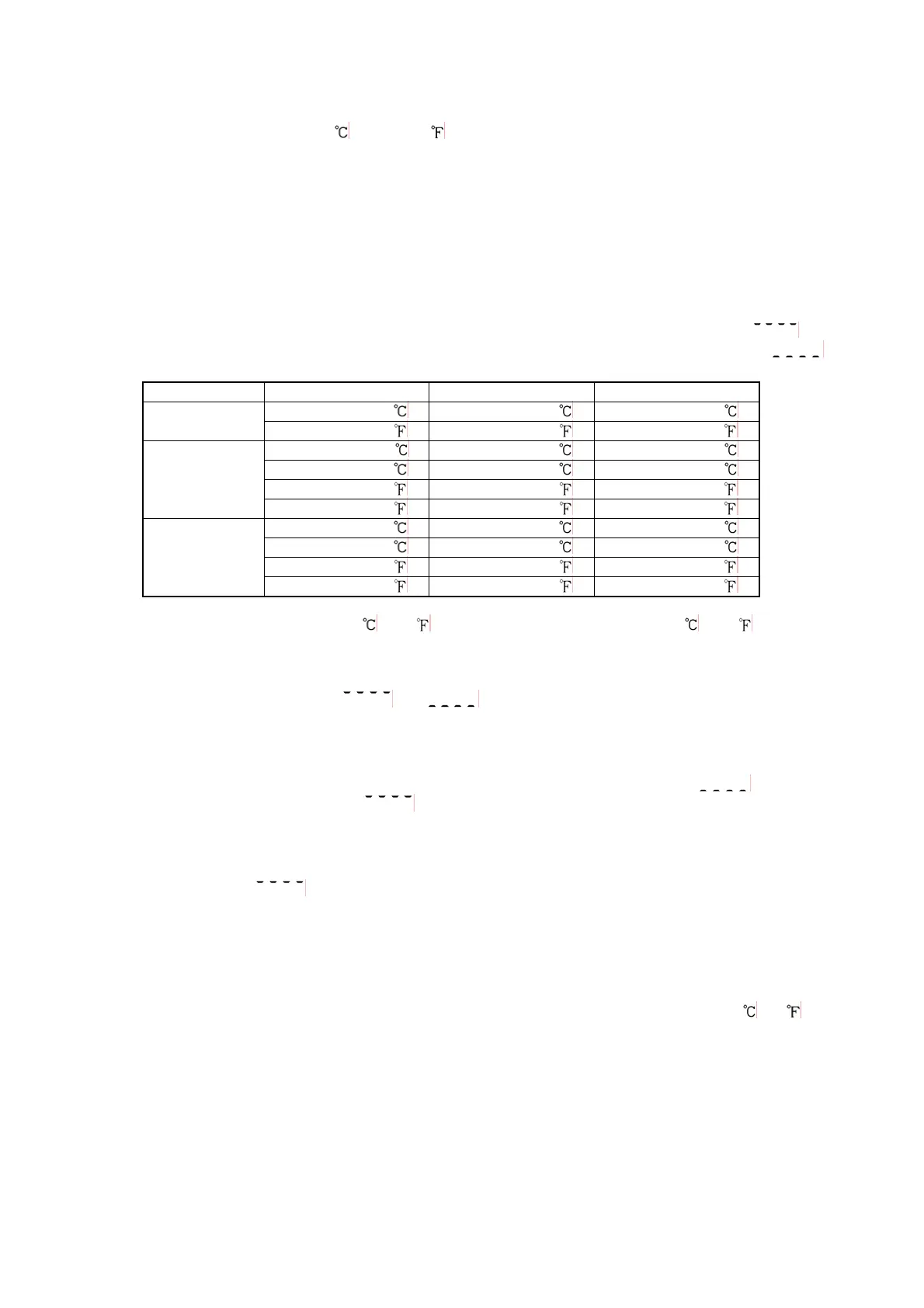
Input Input range Indication range Control range
–199.9 to 400.0 –199.9 to 450.0 –205.0 to 450.0
K,T
–199.9 to 750.0
–199.9 to 850.0 –209.0 to 850.0
–199.9 to 850.0 –199.9 to 900.0 –210.0 to 900.0
–200 to 850 –210 to 900 –210 to 900
–199.9 to 999.9 –199.9 to 999.9 –211.0 to 1099.9
Pt100
–300 to 1500
–318 to 1600 –318 to 1600
–199.9 to 500.0 –199.9 to 550.0 –206.0 to 550.0
–200 to 500 –207 to 550 –207 to 550
–199.9 to 900.0 –199.9 to 999.9 –211.0 to 999.9
JPt100
–300 to 900
–312 to 1000 –312 to 1000
Indication range and Control range for thermocouple inputs other than the above:
Input range low limit value –50
(100 ) to Input range high limit value +50 (100 )
DC input:
Indication range: [Scaling low limit value–Scaling span x 1%] to [Scaling high limit value +Scaling
span x 10%]
However, “
” or “ ” flashes when a range of –1999 to 9999 is
exceeded.
Control range: [Scaling low limit value–Scaling span x 1%] to [Scaling high limit value +Scaling
span x 10%]
DC input disconnection: When DC input is disconnected, the PV display flashes “
” for 4 to 20mA
DC and 1 to 5V DC inputs, and “
” for 0 to 1V DC input. For 0 to 20mA DC, 0 to 5V DC and 0 to
10V DC inputs, the PV display indicates the value corresponding with 0mA or 0V input.
[Burnout]
When the thermocouple or RTD input is burnt out, OUT (Limit control output) is turned off and the PV
display flashes “
”.
[Self-diagnosis]
The CPU is monitored by a watchdog timer, and when an abnormal status is found on the CPU,
the controller is switched to warm-up status.
[Automatic cold junction temperature compensation] (Only thermocouple input type)
This detects the temperature at the connecting terminal between the thermocouple and the instrument,
and always maintains at the same status as when the reference junction is located at 0
(32 ).
[Power failure countermeasure]
The setting data is backed up in the non-volatile IC memory.
[Warm-up indication]
After the power supply to the instrument is turned on, the sensor input characters and temperature
unit are indicated on the PV display, and input range high limit value is indicated on the SV display
for 3 seconds. For DC current and voltage input, scaling high limit value is indicated.
Accessories: Screw type mounting brackets 1 set
Instruction manual 1 copy

 Loading...


