2
1. Model
1.1 Model
JCS–33 A – R / M T6080 , W48 x H48 x D95mm
A1 A A1 output (Alarm type can be selected by keypad) *1
OUT R Limit control output (Relay contact: 1a)
Input M Multi-range *2
Control action T6080 High limit or low limit control action
100 to 240V AC (standard)
Supply voltage
1 24V AC/DC *3
A2 A2 output (Alarm type can be selected by keypad) *1
C5 Serial communication (RS-485)
SM External reset input
TC Terminal cover
Option
BK Color Black
*1: Alarm actions (9 types and No alarm action) and Energized/Deenergized can be selected by keypad.
*2: Thermocouple, RTD, DC current, and DC voltage can be selected by keypad.
*3: Supply voltage 100 to 240V AC is standard. When ordering 24V AC/DC, enter “1” after the input code.
1.2 How to read the model label
Model labels are attached to the
case and the inner assembly.
(1) Model
(2) Option, supply voltage
(“1” is entered only for 24V AC/DC)
(3) Serial number (Only on inner assembly)
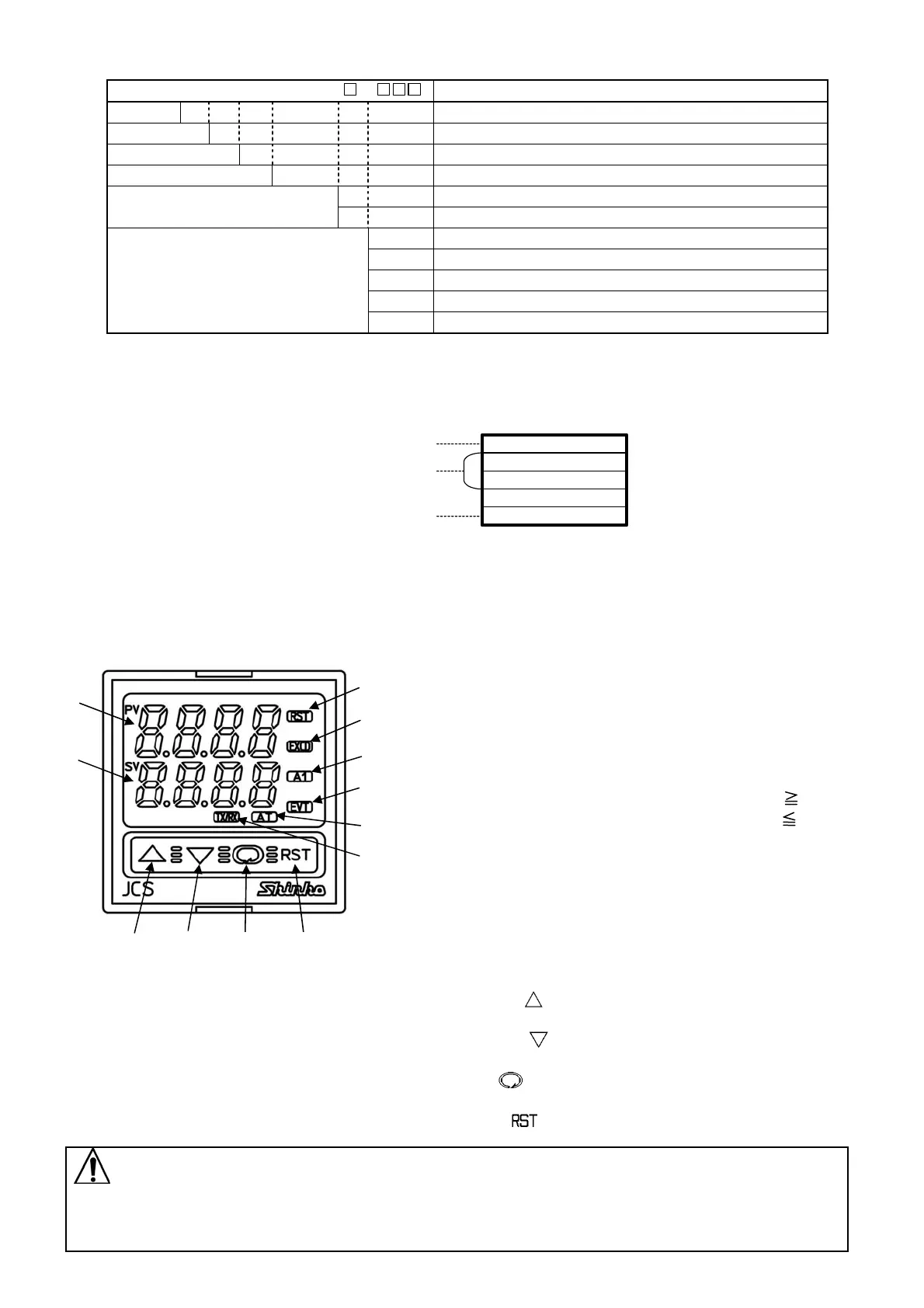
2. Name and functions of the sections
(1) PV display:
Indicates the PV (process variable) with a red LED.
Indicates setting item characters during the setting mode.
(2) SV display:
Indicates the SV (desired value) with a green LED.
Indicates set (or selected) value during the setting mode.
(3) RST(RESET) indicator: Lights when OUT (Limit control
output terminals between 6 and 7) is OFF with a green LED.
(4) EXCD(EXCEEDED) indicator:
High limit action: The yellow LED lights when PV SV.
Low limit action: The yellow LED lights when PV SV.
(5) A1 indicator : When A1 output is ON, the red LED lights.
(6) EVT indicator:
When A2 output (A2 option) is ON, a red LED lights.
(7) AUTO indicator: The yellow LED flashes for auto-start
of the Limit control action.
(8) TX/RX indicator:
The yellow LED lights during Serial communication TX
output (sending) (C5 option).
(Fig. 2-1) (9) Increase key(
): Increases the numerical value, and
switches the setting item during the setting mode.
(10) Decrease key(
): Decreases the numerical value, and
switches the setting item during the setting mode.
(11) Mode key(
): Switches Indication selection mode or
setting mode, and registers the set (selected) value.
(12) RESET key(
): High limit or low limit control action initiates.
Notice
When setting the specifications and functions of this controller, connect terminals 1 and 2 for power
source first, then set them referring to Chapter “5. Settings” before performing “3. Mounting to the
control panel” and “4. Wiring”.
(1)
(2)
(9)
(10)
(11)
(12)
(3)
(4)
(5)
(6)
(7)
(8)
Relay contact output /Multi-range input
(1)
(2)
(Model label)
(e.g.)
(3)
JCS-33A-R/M T6080
No. A55000
A2 outputA2
MULTI RANGE

 Loading...


