3
3. Mounting to the control panel
3.1 Site selection
Caution
• Use within the following temperature and humidity ranges.
Temperature: 0 to 50
(32 to 122 ), Humidity: 35 to 85%RH (No condensation or icing)
• When this unit is installed through the control panel, the ambient temperature of this unit as well as
the control panel must be kept to under 50
. Otherwise the life of electronic components (especially
electrolytic capacitors) will be shortened.
This instrument is intended to be used under the following environmental conditions
(IEC61010-1): Overvoltage category
, Pollution degree 2
Ensure the mounting location corresponds to the following conditions:
• A minimum of dust, and an absence of corrosive gases
• No flammable, explosive gases
• Few mechanical vibrations or shocks
• No exposure to direct sunlight, an ambient temperature of 0 to 50 (32 to 122 )
that does not change rapidly
• An ambient non-condensing humidity of 35 to 85%RH
• No large capacity electromagnetic switches or cables through which large current flows
• No water, oil or chemicals or where the vapors of these substances can come into direct
contact with the controller
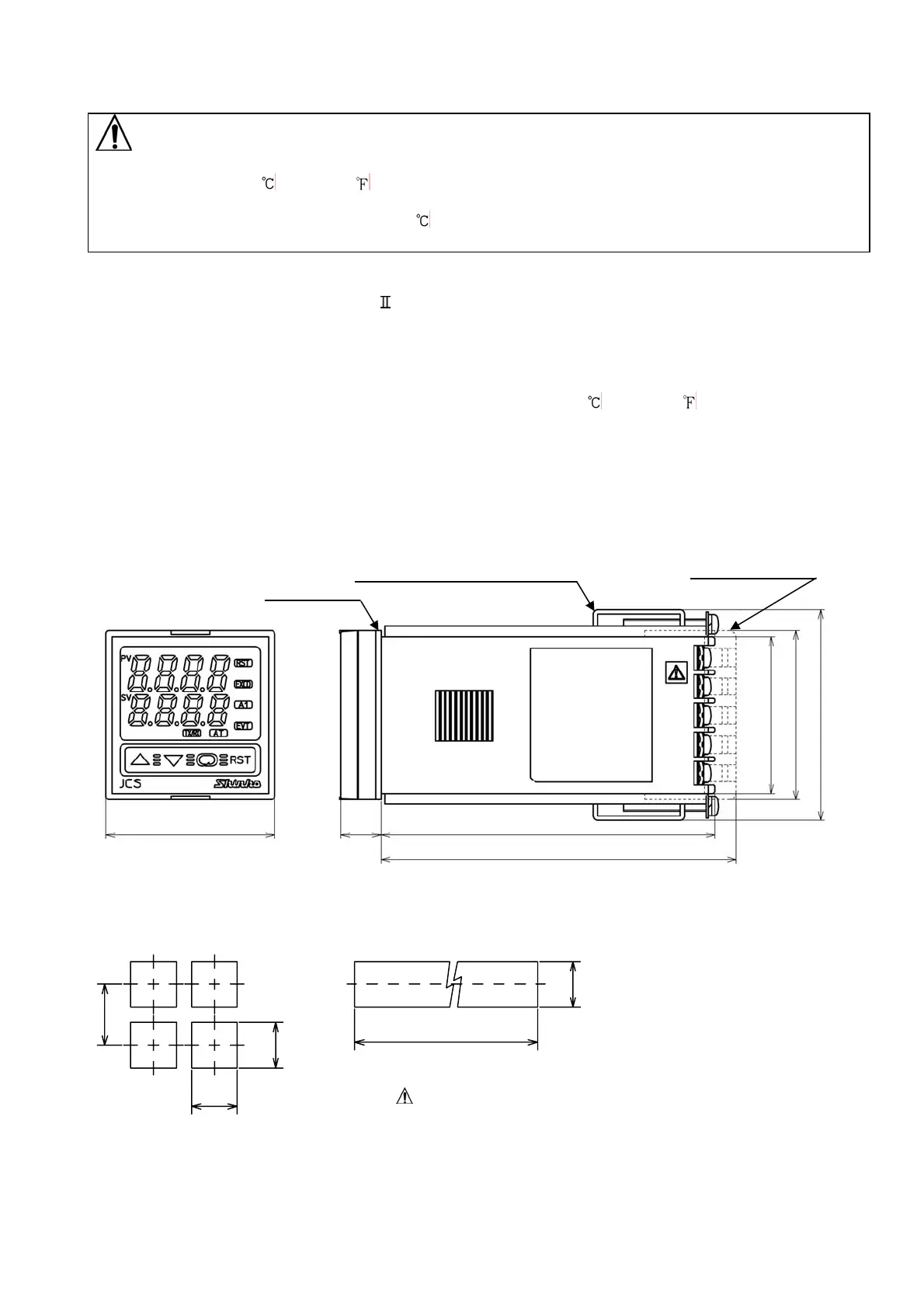
3.2 External dimensions (Unit: mm)
(Fig. 3.2-1)
3.3 Panel cutout (Unit: mm)
Lateral close mounting
n: Number of units mounted
Caution: If lateral close mounting is used for the controller,
IP66 specification (Dust-proof/Drip-proof) may be
compromised, and all warranties will be invalidated.
(Fig. 3.3-1)
75
45
+0.5
0
45
+0.5
0
45
+0.5
0
n x 48-3
+0.5
0
Gasket
Screw type mounting bracket
Terminal cover (*)
□48
□44.5
48 (*)
59.7
11.5 95
101 (*)
(*) For TC option

 Loading...


