EasyManua.ls Logo

Shinko PCB1 - User Manual

Shinko PCB1
160 pages
Print Icon
To Next Page IconTo Next Page
Loading...
PROGRAMMABLE CONTROLLER
PCB1
INSTRUCTION MANUAL

Table of Contents

Questions and Answers

  • P
    phillipcraneAug 20, 2025
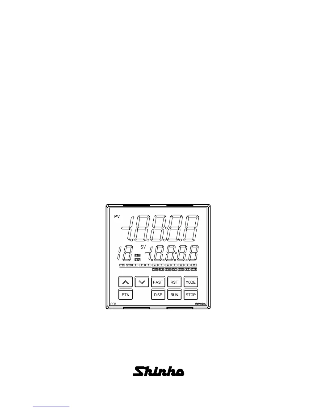
    What to do if PV and er05 are alternately displayed on Shinko PCB1?
    • J
      Jillian MurilloAug 20, 2025
      If the PV Display indicates PV and er05 alternately, it means there's an overscale issue. The PV has exceeded the input range high limit value, which is the scaling high limit value for DC voltage or current inputs. Check the input signal source.
  • N
    Nancy ShawAug 22, 2025
    Why does my Shinko Controller show PV and er06 alternately?
    • S
      Shane BurnsAug 22, 2025
      If the PV Display indicates PV and er06 alternately, it indicates an underscale issue. The PV has dropped below the input range low limit value, which is the scaling low limit value for DC voltage or current inputs. Check the input signal source and the wiring of the input terminals.
  • B
    Bruce BarnesAug 27, 2025
    What should I do if my Shinko Controller PV Display flashes and shows [er07]?
    • J
      jkimAug 27, 2025
      If the PV Display flashes and indicates [er07] alternately, it means the PV has dropped below the indication range and control range. Check the input signal source and wiring of input terminals.
  • E
    elizabethriveraAug 28, 2025
    Why is the PV Display indication irregular or unstable on my Shinko PCB1 Controller?
    • T
      timothyjohnsonAug 28, 2025
      An irregular or unstable PV Display indication can be caused by several factors: * Incorrect sensor input or temperature unit ( or ). Make sure to select the correct sensor input and temperature unit. * Unsuitable sensor correction coefficient or value. Set them to suitable values. * Incorrect sensor specification. Use a sensor with appropriate specifications. * AC leaking into the sensor circuit. Use an ungrounded type sensor.
  • M
    Maria MaysAug 29, 2025
    Why does the PV value not rise or fall on my Shinko PCB1 Controller?
    • C
      Courtney VelazquezAug 30, 2025
      If the PV value does not rise or fall, the sensor may be out of order, so replace the sensor. Also, check that the sensor or control output terminals are securely mounted to the instrument input terminals and that the wiring of sensor or control output terminals is correct.
  • J
    John Wilson DVMSep 2, 2025
    Why is the step not progressing on my Shinko PCB1 Controller?
    • M
      micheleperezSep 3, 2025
      If the step isn't progressing, it could be due to a couple of reasons: * Program control is suspended (Hold function). If the PV Display and RUN indicator are flashing, press the RUN key to cancel the suspension and resume program control. * The Wait function is active. If the PV Display and PTN/STEP Display are flashing, press the RUN key for approximately 1 second to cancel the Wait function, allowing program control to continue.
  • S
    sarabarkerSep 4, 2025
    Why does the program finish too quickly on my Shinko Controller?
    • J
      John CameronSep 4, 2025
      If the program control is advancing too quickly and finishing sooner than expected, the step time of the performing pattern number may be set to 00:00. Set the step time to a suitable value.
  • J
    jenniferglennSep 6, 2025
    What does er20 mean on my Shinko Controller PV Display?
    • J
      Joseph MatthewsSep 6, 2025
      If the PV Display indicates er20, it means that AT has not been completed even if approximately 4 hours have elapsed since AT started. You should manually set P, I, D, and ARW values.
  • A
    Anna BlankenshipSep 8, 2025
    Why is the control output OUT1 or OUT2 always ON on my Shinko PCB1 Controller?
    • A
      andreabenderSep 8, 2025
      If control output OUT1 or OUT2 remains constantly ON, the OUT1 or OUT2 low limit value may be set to 100% or higher. Set it to a suitable value.
  • Z
    zcohenSep 10, 2025
    Why is the control output OUT1 or OUT2 always OFF on my Shinko Controller?
    • M
      martinangelaSep 10, 2025
      If the control output OUT1 or OUT2 remains constantly OFF, the OUT1 or OUT2 high limit value may be set to 0% or less. Set it to a suitable value.

Summary

Preface

Abbreviations used in this manual

Lists abbreviations for terms like PV, SV, MV used in the manual.

Notes

Provides important usage instructions, warnings, and disclaimers for the controller.

Safety Precautions

General Safety & Warnings

Covers warnings, cautions, and general safety advice for device operation.

Installation Safety

Details environmental conditions and precautions for safe panel mounting.

Handling Precautions

Wiring Precautions

Lists safety guidelines and best practices for electrical wiring.

Operation & Maintenance Precautions

Advises on safe operation, cleaning, and maintenance procedures.

Model Information

Model Details

Explains the model designation and its components.

Model Label Interpretation

Describes how to read and understand the information on the unit's model label.

Controller Components

Displays and Indicators

Explains the function of each display segment and indicator light on the controller.

Key Functions

Details the purpose and operation of each button on the controller's interface.

Connectors

Identifies and describes the function of the unit's external connectors.

Installation & Mounting

Dimensions & Panel Cutout

Provides external dimensions and panel cutout details for installation.

CT Dimensions

Shows external dimensions for Current Transformer (CTL-6-S-H and CTL-12-S36-10L1U).

Mounting;Removal Procedures

Describes the process for attaching and detaching the controller from a control panel.

Wiring Guide

Wiring Precautions

Lists safety guidelines and best practices for electrical wiring.

Terminal Arrangement

Details the layout and function of each terminal connection on the controller.

Wire Terminals & Covers

Explains the use of solderless terminals and terminal covers for wiring.

Wiring Connections Overview

Summarizes various wiring configurations for power supply, outputs, and inputs.

Operation Modes & Controls

Key Operation Outline

Provides a flowchart and description of key operations and mode transitions.

Operating Modes Description

Explains the different operating modes (RUN, Monitor, Setting) and their functions.

Settings Management

Describes how to register settings, navigate menus, and return to RUN mode.

Initial Configuration

Initial Settings Procedure

Details the steps for initial setup in Engineering and Control parameter modes.

Basic Operations

Basic Settings & Operation Flow

Outlines the sequence for basic configuration and operation.

Program Pattern Setting

Explains how to set up program patterns for sequential control.

Setting Item Explanations

Pattern Setting Mode Items

Details how to set Step SV, Step time, and PID block numbers for program patterns.

Event Setting Mode Items

Explains how to configure event outputs, alarm values, and time signals.

Control Parameter Mode Items

Describes settings for AT, PID blocks, and control actions like Direct/Reverse.

Wait Parameter Mode Items

Covers setting Wait value and enabling/disabling wait functions for program steps.

Engineering Mode 1 Items

Details settings for value lock, sensor correction, and communication parameters.

Engineering Mode 2 Items

Covers input types, scaling, decimal points, and event output allocations.

Data Clearing Procedure

Explains how to reset the unit to factory default values.

Operational Procedures

Program Control Execution

Describes methods for starting and managing program control sequences.

Fixed Value Control

Explains how to perform and finish fixed value control operations.

SV Display Switching

Details how to cycle through different indications on the SV display.

Auto-Tuning (AT) Procedure

Explains how to perform AT and its impact on control parameters.

Input Value Correction

Describes how to adjust input values using sensor correction methods.

Settings Initialization by Changes

Shows which settings are reset when other parameters are modified.

Action Explanations

OUT1 Control Actions

Explains the behavior of OUT1 for heating/cooling and ON/OFF control.

Heater Burnout Alarm

Describes the action taken when a heater burnout condition is detected.

Alarm Action Types

Illustrates various alarm conditions and their output actions.

OUT2 Heating;Cooling Actions

Explains OUT2 behavior for heating/cooling control with dead/overlap bands.

Product Specifications

Standard Specifications

Lists the technical specifications for the controller's performance and structure.

Optional Specifications

Details the specifications for various optional features and communication.

Attached Functions

Describes additional features like sensor correction, self-diagnosis, and input error handling.

Troubleshooting Guide

Indication Errors

Lists problems related to display indications and their possible causes/solutions.

Key Operation Issues

Covers troubleshooting for problems encountered with button inputs.

Control Errors

Addresses issues where the control action does not behave as expected.

Reference Tables

Error Codes

Provides a list of error codes, their meanings, and occurrence conditions.

Setting Mode Reference

Compiles setting items and their ranges for various configuration modes.

Data Tables for Setup

Program Pattern Table Creation

Guides on how to create and document program patterns.

Data Table Creation

Explains how to create data tables for PID blocks and other settings.

Key Operation Flowchart

Key Operation Flowchart

Illustrates the sequence of operations using the controller's keys.

Shinko PCB1 Specifications

General IconGeneral
TypePCB1
CategoryController
Input Voltage24 VDC
Output Voltage5 VDC
Current Rating1 A
Operating Temperature0 to 50°C
Weight200 g
ManufacturerShinko

Related product manuals