- 29 -
6. Initial Settings
Setup (setting the Input type, Scaling high limit, Scaling low limit, Event output EV1 allocation, Step time
unit, Power restore action, Direct/Reverse action, etc.) should be done before using this controller,
according to the user’s conditions.
Perform setup (or initial settings) in Engineering setting mode 2 and Control parameter setting mode.
Initial setting items and their factory default values are shown below in (Table 6-1).
If the user’s specification is the same as the factory default value of this instrument, or if user’s
instrument has already been installed in a system after initial settings are finished, initial settings are
not necessary.
Proceed to Section “7. Basic Settings and Operation” (p.37).
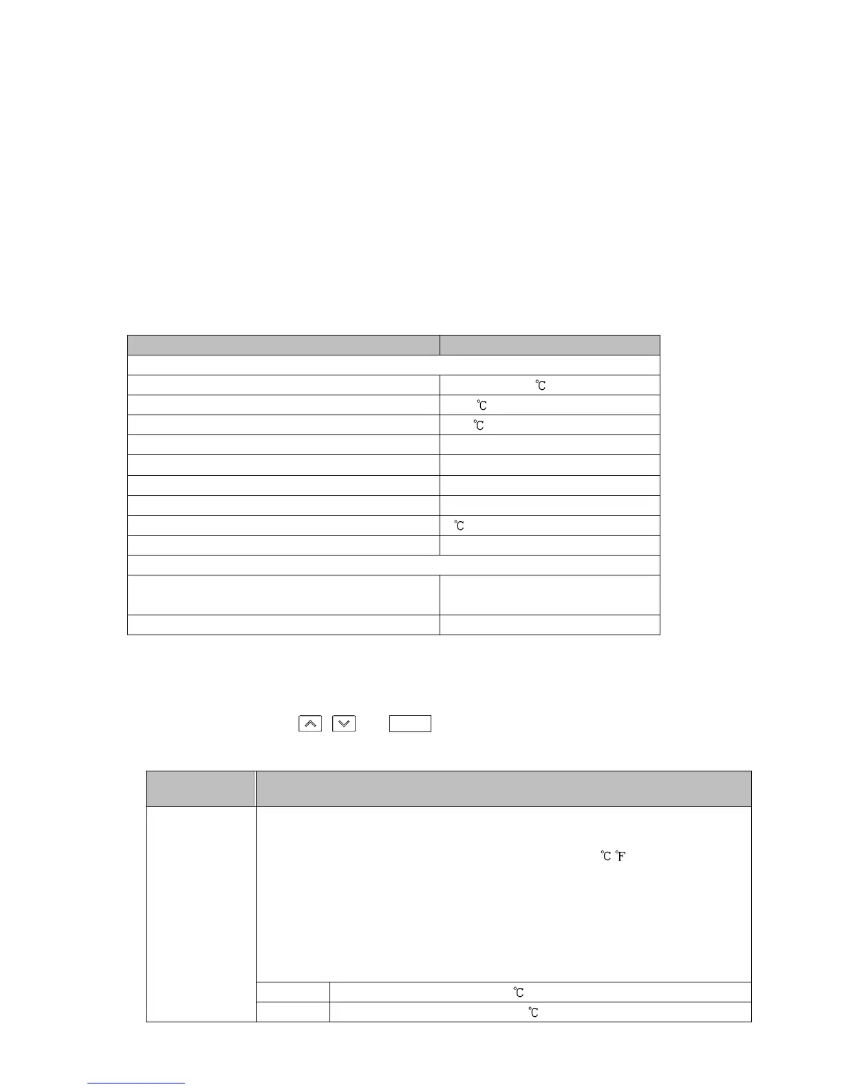
(Table 6-1)
Initial Setting Item Factory Default
Engineering setting mode 2
Input type K -200 to 1370
Scaling high limit 1370
Scaling low limit -200
Decimal point place No decimal point
Event output EV1 allocation No event
Step time unit Hours : Minutes
Power restore action Stops after power is restored.
Step SV when program control starts 0
Program control start type PV start
Control parameter setting mode
OUT1 proportional cycle Relay contact output: 30 sec
Non-contact voltage output: 3 sec
Direct/Reverse action Reverse action
The following shows the procedure for initial settings.
(1) Enter Engineering setting mode 2.
In the RUN mode, press , and MODE keys (in that order) together for approx. 3 seconds.
The unit will enter Engineering setting mode 2.
Factory Default
Setting Item, Function, Setting Range
sens
/ k//C
Input type
• Selects an input type from thermocouple (10 types), RTD (2 types), direct
current (2 types) and DC voltage (4 type), and the unit / .
• When changing the input from DC voltage to other inputs, remove the
sensor connected to this controller first, then change the input. If the
input is changed with the sensor connected, the input circuit may break.
• When changing an input type, refer to Section “9.6 Items to be Initialized by
Changing Settings” (p.104).
• Selection item:
k//C K -200 to 1370
k//.C K -200.0 to 400.0