- 23 -
4.4.7 CT Input 1 and CT Input 2
Current Transformer (CT) input is available when Heater burnout alarm output (C5W, EIW,
W options) is ordered.
Cannot be used for detecting heater current under phase control.
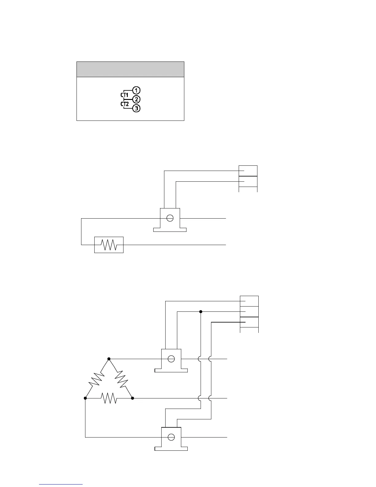
Current Transformer (CT) Input 1
Current Transformer (CT) Input 2
Use the CT (current transformer) provided, and pass one lead wire of the heater circuit
into the hole of the CT. (Fig. 4.4.7-1)
When wiring, keep the CT wire away from AC sources or load wires to avoid the external
interference.
(Fig. 4.4.7-1)
When using 3-phase, pass any 2 lead wires of R, S, T into the CT, and connect them to
CT1 (①-②) and CT2 (②-③) terminals. (Fig. 4.4.7-2)
(Fig. 4.4.7-2)
Power supply
CT1
Heater
①
②
③
R
S
T
CT2
CT1 input terminal
CT2 input terminal