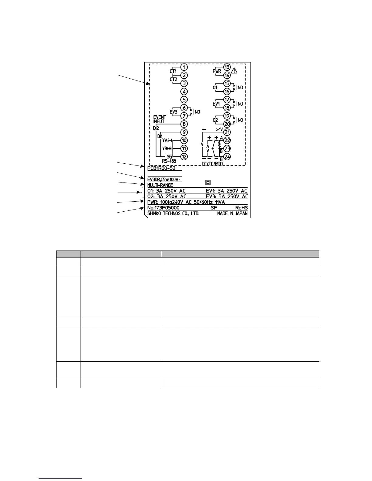
① Terminal arrangement Terminal arrangement of PCB1R00-52 (*1)
② Model PCB1R00-52
③ Option EV3DR (Event output EV3 + Event output EV2, or
Heating/Cooling control output OUT2 Relay contact
output)
C5W(100A) [Serial communication + Heater burnout
alarm output (100 A) + Event input] (*2)
④ Input MULTI-RANGE (Multi-range input)
⑤ Control output,
Event output
O1: 3 A 250 V AC (Control output OUT1)
EV1: 3 A 250 V AC (Event output EV1)
O2: 3 A 250 V AC (Control output OUT2)
EV3: 3 A 250 V AC (Event output EV3)
⑥ Power supply,
Power consumption
100 to 240 V AC 50/60 Hz,
11 VA
⑦ Serial number No. 173F05000
(*1) Terminal arrangement diagram differs depending on the model.
(*2) For Heater burnout alarm output (C5W, EIW, W options), CT rated current is entered in bracket ( ).
①
②
③
⑤
④
⑥
⑦