- 19 -
4.4 Wiring
For the terminal arrangement, refer to Section ‘4.1 Terminal Arrangement’ (p.17).
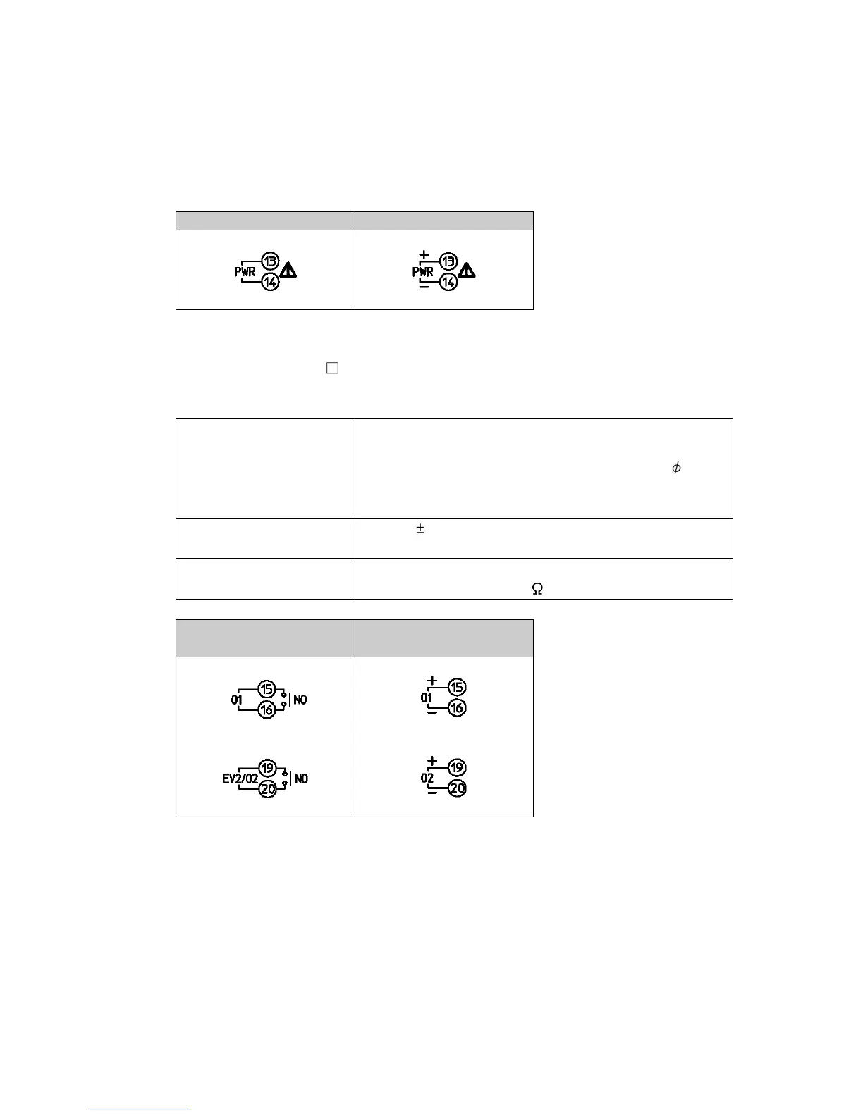
4.4.1 Power Supply
Power supply voltage is 100 to 240 V AC or 24 V AC/DC.
For a 24 V AC/DC power source, ensure polarity is correct when using direct current (DC).
100 to 240 V AC, 24 V AC 24 V DC
4.4.2 Control Output OUT1 and OUT2
When EV2, DS, DA or EV3D option is ordered, control output OUT2 is available.
Specifications of Control output OUT1 and OUT2 are shown below.
Relay contact 1a
Control capacity: 3 A 250 V AC (resistive load),
1 A 250 V AC (inductive load cos =0.4)
Electrical life: 100,000 cycles
Minimum applicable load: 10 mA 5 V DC
Non-contact voltage
(for SSR drive)
12 V DC 15%
Max. 40 mA (short circuit protected)
Direct current 4 to 20 mA DC
Load resistance: Max. 550
Relay contact
Non-contact voltage,
Direct current
Number of Shinko SSR units when connected in parallel (for Non-contact voltage output):
• SA-400 series: 5 units
• SA-500 series: 2 units