- 17 -
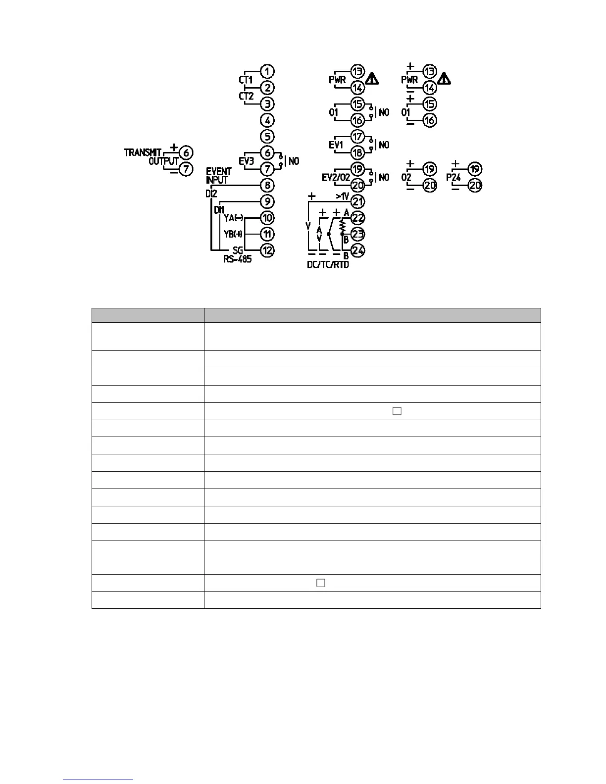
4.1 Terminal Arrangement
(Fig. 4.1-1)
Terminal Code Description
PWR Supply voltage 100 to 240 V AC or 24 V AC/DC
(For 24 V DC, ensure polarity is correct.)
O1
Control output OUT1
EV1
Event output EV1
EV2
Event output EV2 [EV2, EV3(DR) options]
O2
Control output OUT2 (EV2, DS, DA, EV3D options)
P24
Insulated power output 24 V DC (P24 option)
TC
Thermocouple input
RTD
RTD input
DC
Direct current, DC voltage input
CT1
CT (current transformer) input 1 (C5W, EIW, W options)
CT2
CT (current transformer) input 2 (C5W, EIW, W options)
RS-485
Serial communication RS-485 (C5W, C5 options)
EVENT INPUT
Event input DI1 (C5W, EIW, EIT, C5, EI options)
Event input DI2 (C5W, EIW, EIT, C5, EI options)
EV3
Event output EV3 (EV3D , EI options)
TRANSMIT OUTPUT
Transmission output (EIT option)